 Brian Gally from Nanoco described an exciting new QD architecture where the quantum dots are placed in the color filters of the LCD and not in a sheet (and that we first reported on last year at SID when it was proposed by Nanosys (BC19 Nanosys Changes QD LCD Architecture). With the QD sheet implementation, white light is created in the backlight, modulated by the LCD and filtered by the LCD panel. Each sub-pixel can lose around two-thirds of the light hitting it to create a red, green or blue sub-pixel. If the quantum dots are placed in the color filters with only a blue LED backlight, that has some very positive benefits which Gally listed as better color, higher efficiency, wider viewing angles and improved contrast. These benefits could be very significant allowing an LCD to have 2-2.5X higher brightness at the same power level as a conventional LCD, or offer a display with similar brightness but greatly reduced energy consumption.
But there are some major challenges to realizing such a display. These include device development (in-cell polarizer, reflectors etc.) and material development (patternable QD-resin, high concentration of QD in resin, air ambient processability).
Gally then cited a number of research efforts to develop QD materials for use in color filters, but he did not describe the efforts underway at Nanoco.
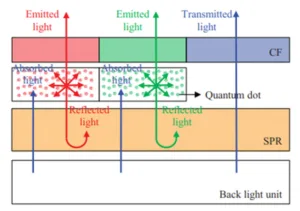
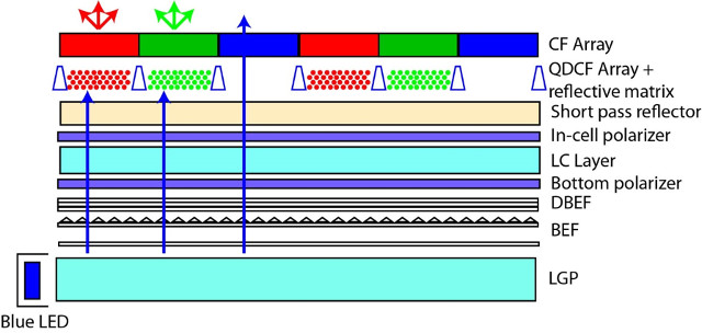
The device challenges are formidable. For one, quantum dots emit in a spherical pattern so some of the light will go sideways and some will head back toward the display. A reflector will be needed to send this backward heading light out toward the viewer again. The sideways headed light may require that the quantum dots be placed in wells to prevent light leakage. And, you will need an in-cell polarizer since the color conversion process also depolarizes the light. You can’t use the simple sheet polarizers used today. Finally, it seems likely you may need a color filter as part of the stack also as ambient light from the room might cause emission of the quantum dots if this is not some absorption of this light. The result is the ideal architecture shown below.
Gally then went into more detail about Nanoco’s QD manufacturing process which they call molecular seeding. This is different from the approach that Samsung uses. Nanoco use molecular cluster compounds to nucleate nanoparticle growth. Then, precursors are added periodically to promote particle growth. The advantages of this approach are said to be that it is inexpensive using readily-available precursors, there are no harsh conditions and it is easy to control.
Current Nanaco quantum dot materials achieve FWHM of < 50nm for the red, FWHM of < 40nm for the green with a photoluminescent quantum yield of > 80%. Over the last two years, they have seen reactor yield increase significantly as well (> 8-fold for red and> 6-fold for green).
As for the approaches that can be used to make QD color filters, Gally outlined two methods. One way is to embed the QDs in photoresist, but this is a subtractive process so likely to be more expensive – certainly from a materials point of view. Alternatively, inkjet printing will be more efficient with these expensive materials and this equipment is coming in line now for OLED production, but it may require the formation of walls to hold the material until it cures (and reduce cross talk).
In the panel session, Gally and Jang both commented that it would be 2-3 years before this technology can be commercialized in displays.