You may have noticed that I enjoy taking apart TVs and understanding the optical materials on the inside. While this isn’t exactly possible during a trade show, I can point my spectrometer at them and get some clues about the inner workings.

Today I’m revisiting some data I captured during SID Display Week 2022 along with data that others presented during the conference. I pay particularly close attention to the light generation and light conversion part of displays, where phosphors and QDs tend to be the two dominant color converting technologies we hear about in displays. While often they compete against each other, today I have three examples of where QDs and phosphors are working in harmony to improve displays.
Example 1:
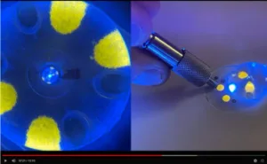
To set the stage, I will first point out an interesting finding I made during one of my TV teardown videos. Taking apart a TCL 5-series I came across YAG phosphor printed in four dots around the blue LED in a FALD TV. It’s weird enough to have the phosphor printed next to the LED, but to find this in a TV that contains a QD film is even more strange. My hypothesis is that it improves brightness or color uniformity in some way. (Pete Palomaki Tears Down Another Broken TV – registration required).
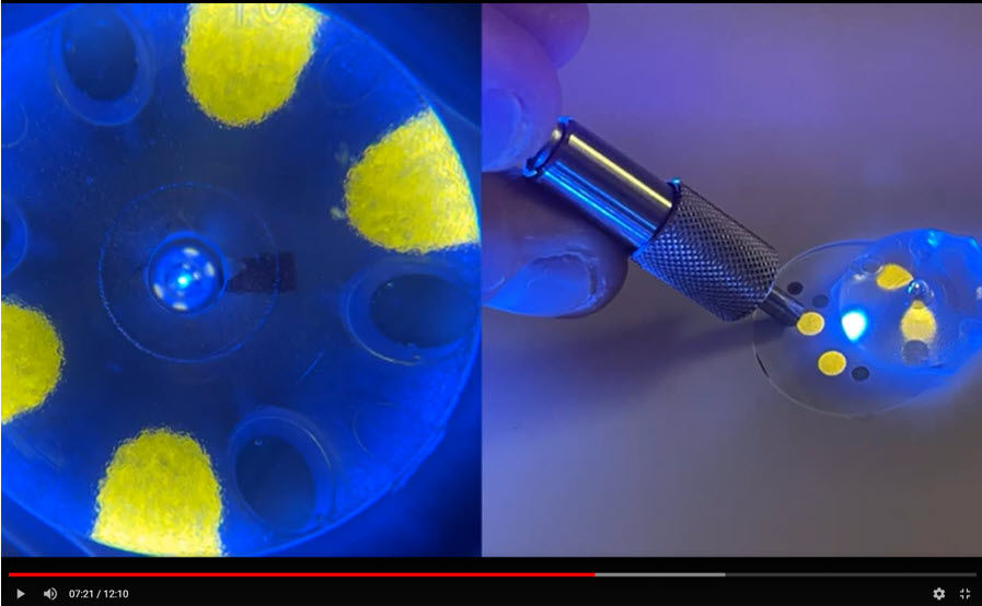 YAG phosphor printed next to a blue LED in a TCL QLED TV. Source: https://www.youtube.com/nanopalomaki
This was the first TV I analyzed on my channel that contained both QDs and phosphors. Before this most consumers were under the impression that TVs branded as QLED (or some other quantum, QD, etc. marketing phrase) contained QDs driven by a blue LED and no phosphor, while all remaining LCD TVs (not branded as QD) contained only phosphor on a blue LED. Now we have a better understanding that a QD-branded TV may contain more than just QDs. Let’s move on to the next example.
Example 2:
I analyzed a TV at SID Display Week in the Nanosys booth. Recall that Nanosys received a “Component of the Year” award for their extruded diffuser plate containing QDs (xQDEF) which is being implemented in lower price point TVs. The xQDEF diffuser plate serves two purposes; color conversion and diffusion (eliminating hot spots from LEDs). Nanosys was kind enough to allow me to measure the emission spectrum of the part in their booth, along with the Hisense U6G TV that hung alongside the xQDEF diffuser plate demo. This TV contains the xQDEF part and was highlighted as an inexpensive ($500) TV containing QDs.
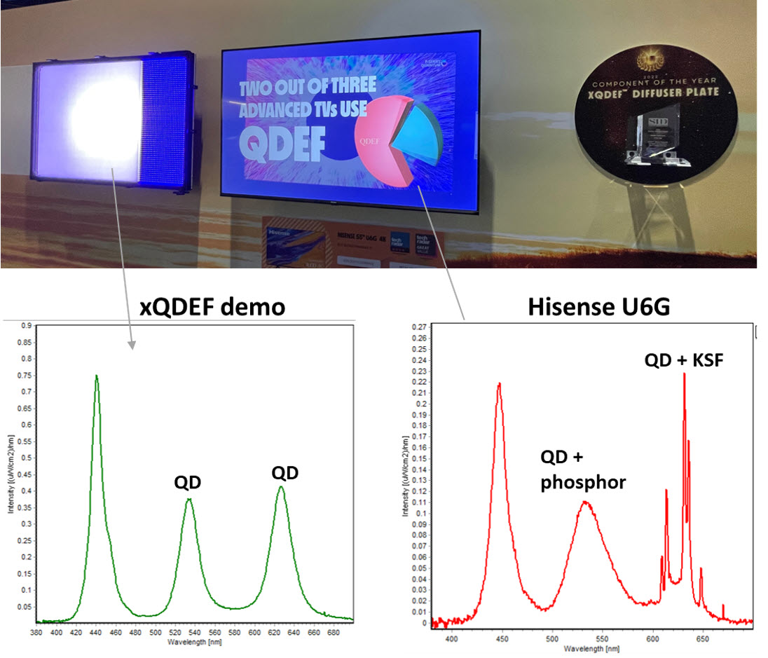 Photo and spectral analysis of the xQDEF part and Hisense U6G TV in the Nanosys booth. The green peak shows ~45nm FWHM in Hisense U6G compared to <25 nm in xQDEF demo. Source: Palomaki Consulting
As you can see in my spectral analysis, the xQDEF part does indeed show two pure emission peaks originating from QDs (in addition to the blue LED peak). However, when I measured a whiteish area of the Hisense TV I saw a much different story. The green peak was much broader than one would expect from QD emission. The red peak is quite clearly dominated by KSF phosphor (based on unique optical fingerprint). The only reasonable conclusion I can come to (without tearing it apart) is that the LEDs inside the Hisense TV contain KSF and a green phosphor on chip while the xQDEF part contains QDs. That would be 4 down-converters inside one TV!
Example 3:
The third example is not my own, but was presented at SID Display Week by GE (inventors of KSF for which a license is required to use in displays). They showed a configuration strikingly similar to the one I measured in the Nanosys booth which helps give me confidence in my findings. In this TV (model not stated) GE found KSF and green phosphor on the LED, while the QD diffuser plate contained both green and red QD emission. The front of screen spectra is strikingly similar to what I found at the Nanosys booth.
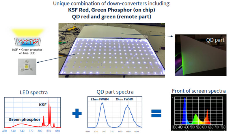 GE’s analysis of a TV containing both QDs and phosphors. Source: GE presentation, SID 2022
Given that the approach of QDs and phosphors together is somewhat new, I thought I would go directly to the source for some input. Nanosys and GE.
I reached out to Nanosys about my findings and learned the following (summary in my own words): There exist two versions of the xQDEF diffuser plate. A “low concentration” version, and a “full concentration” version. The version in the Hisense TV is the low concentration version which means additional color-converting material is also required (i.e. phosphors). Both versions contain cadmium but they are RoHS compliant. Including QDs in the form of xQDEF diffuser plate with phosphors provides advantages in response time, color gamut, and optical diffusion in FALD backlight.
I also reached out to GE about my findings – which were quite similar to their findings – and learned the following (summary in my own words): KSF does not technically have a FWHM peak width metric since it is 5 individual super-narrow peaks, but it actually provides better color and performance (EQE) compared to the 35 nm FWHM QD used in the remote part measured by GE. KSF has excellent reliability so can also be used on-chip without encapsulation. Implementing KSF may also have a benefit by lowering QD (Cd) usage in the part, making it more likely to be RoHS compliant as well as less expensive. Using a hybrid approach of pairing red KSF with green QD realizes the best color performance possible with existing down-converter technology.
These comments got me thinking so let me take you down the rabbit hole for a moment.
If KSF provides the best color for red, and QDs provide the best color for green, why not simply implement a “magenta” LED with KSF on chip paired with a QD part containing only green QDs? Nanosys pointed out relaxation time but GE will tell you this is a non-issue since the LCD is the slowest component. I think there is another factor at play here. My suspicion is that the color as a function of angle will be negatively impacted if the design has one color coming from the LED and the other in the remote part. The emission of photons from the LED+phosphor has a certain angular distribution.
This angular distribution is likely to be different than the angular distribution of photons coming from the QD part. If only red is used on chip, and only green QD is used in the remote part then the color could be different depending on the viewing angle. By using both red and green phosphor on chip paired with both red and green QD in a remote part means the change in color as a function of angle will remain similar (for red and green at least). I have absolutely zero data to back this up at the moment, but I think my logic is sound.
My final thoughts on the matter: I think it’s awesome that the industry is embracing multiple down-converting materials working in concert to create even better (and cheaper) displays. I expect more of these in the future as the display community continues to innovate with improvements in materials and processes. (PP)
Peter Palomaki is the owner and chief scientist at Palomaki Consulting, a firm specializing in helping companies solve big problems at the nanoscale. His utilizes his expertise in quantum dots and materials chemistry to solve challenging problems with clients large and small.