meBroadcast & Distribution – On November 18th, the New York chapters of SMPTE and IEEE-BTS and the Mid-Atlantic chapter of the SID held a joint meeting titled “The Calibration Conundrum – Display Measurement in the Post-Phosphor Era”

There were three speakers:
-
Gary Mandle is Senior Product Manager in the Display Systems Group of Sony Electronics. He has worked with CRT, SXRD (LCoS), LCD, and now OLED products.
- Matthew Donato is a student at the Rochester Institute of Technology. While he’s an undergraduate just finishing his degree in Motion Picture Science, he is the first student to be a full voting member on a SMPTE technical standards committee.
- Bill Miller is a consultant and principal of Miltag Media Technology. He has a long history of involvement with SMPTE and IEEE-BTS. He spoke at the meeting in his capacity as Chairman of SMPTE 10E-fpm, the Drafting Group on Reference Displays and Reference Viewing Environment.
In the past, virtually all displays were phosphor based, i.e. they were CRTs. These high-end CRTs were used for color grading of content, especially content for broadcast applications. When high-end CRTs became unavailable 10 years ago or so, many content creators switched from CRTs to plasma displays, which used pretty much the same phosphors as CRTs and therefore had more or less the same colorimetry.
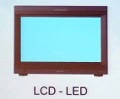
This era of uniform technology and colorimetry for displays, even for reference monitors used for color grading of content in post-production houses, has ended. A few CRTs and plasma displays are in use but LCD displays with both CCFL and LED backlights, and OLED reference displays are more the norm.
The first problem comes when setting the white point of the display, the first step in preparing to color-grade content in a post-production house is to set the white point on the reference display. Typically, the display is set up to a D65 white point, x = 0.3127, y = 0.290.
When you set up two CRTs to these x-y color coordinates, typically they look the same. When you set up a CRT side-by-side with an LCD or an OLED display to these x-y color co-ordinates, the three displays look different.
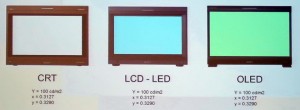
Mandle presented an image showing this problem, with three displays set up to the same x-y white point but showing different colors. This image is not color accurate – it is a photo off the projection screen of a PowerPoint slide. But apparently the difference in white point is visible to ordinary eyes, not just the “Golden Eyes” of post-production colorists.
Mandle and Donato presented convincing data that the root problem is not in the instruments used to set the x-y values of the white point but in the CIE 1931 color matching system these instruments are based on. The CIE 1931 color matching system is based on the CIE 1924 luminance matching system, which was in turn based on data measured in the decade or so before 1924. So some of the data behind the CIE 1931 system is nearly 100 years old now.
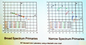
The problem is called “Metamerism Failure” and the problem gets worse with narrow spectrum primary colors (e.g. LEDs and OLEDs) compared to displays with broad spectrum primaries (e.g. CRTs). Since mostly broad spectrum primaries were available to researchers in the years before 1931, its not surprising the CIE 1931 system works best for broad spectrum primaries. The image shows measured colors of Macbeth color chart chips. The color points should all form a straight line and when illuminated with broad spectrum primaries, they do. With narrow spectrum primaries, well, they don’t. The ultimate in narrow spectrum primaries is laser primaries, essentially prescribed by ITU-R Recommendation BT.2020 for UHD-TV, so the problem is only going to get worse, not better.
 Using “newer” color matching systems doesn’t fix the problem. Mandle showed Sony data that when using color matching curves based on Judd 1951 the problem was still there. The CIE also offered an update with its CIE 1964 curves. Mandle said these curves applied to a different geometry and didn’t apply to the display white point problem. He added that they had been tried anyway and they, in fact, didn’t work.
Donato, working with David Long, an Associate Professor at RIT, independently performed calculations and experiments similar to the work done at Sony and came to similar conclusions. These conclusions included the fact that for any given display technology and spectrum, the offset of the white point was consistent from display to display in the series.
The CIE 1931 curves are very deeply ingrained in both SMPTE and SID practice. Coming up with new standard curves is likely to be a decades-long process but the SMPTE community needs a solution to this problem now, not decades from now. That’s where Miller’s work on the SMPTE technical committee comes in. SMPTE is in the process of approving a Recommended Practice, RP-2080-2, defining how to set black point and white point on a reference display.
For setting the black point, RP-2080-2 will recommend setting it by eye using a PLUGE (picture line-up generation equipment) test pattern. Setting the white point will be done with a calibrated instrument. If you are setting up to D65 (x = 0.3127, y = 0.290), for example, you won’t expect your meter to read 0.3127, 0.290. Instead, the meter will read 0.3127, 0.290 minus x and y offset values, with the offset values to be supplied by the display manufacturer. This will then ensure all reference displays will look the same to the “typical” viewer.
Of course, not all viewers are “typical” but that’s a separate problem. The speakers repeated horror stories where the Director, the Director of Photography and the Colorist all have different eyes and practically get in fist fights whether two side-by-side displays have the same white point or not. But that’s another problem, even more intractable than setting the white point of the display for the “Typical” viewer. – Matthew Brennesholtz