LUTs (Look Up Tables) are a simple idea. You have two lists and for each value in list one, you have a corresponding value in list 2. When a system or process receives a value in list one, it outputs the value in list 2. So how do they apply to displays?

Well, the idea of a LUT has a long history in digital displays. In the days of the early PCs, such as CGA, the outputs from computers were digital but the monitors were based on CRTs which were fundamentally analogue. That meant that monitors would have internal LUTs that mapped the digital colours (16 in CGA) to particular analogue brightness levels of the monitor.
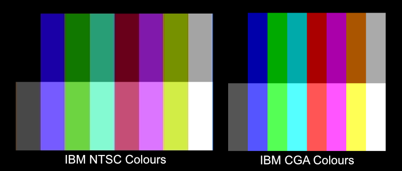
Several decades ago, I got a batch of monitors from Japan that had been mapped to original IBM CGA diagnostic disks, that showed 16 colours including ‘brown’ and it was quite a dark brown. However, when we saw production units of the IBM monitors that patch was yellow and the diagnostics software was changed to match! We told the factory in Japan who sent a batch of new LUTs which were stored in EPROMs and we fitted those in the monitors. From then on, the brown became yellow!
 Different colours with different values in the look up tables between the IBM CGA composite NTSC and TTL modes
Later graphics standards, like VGA allowed the use of analogue monitors, with the graphics card selecting 256 values out of the 16.7 million possible values in the monitor. All of that was in the 80s, so the idea was not new.
The next big development was to integrate very accurate and fine resolution LUTs into the monitors. You could create the values in the LUTs using a calibration system so that the LUT could compensate for any real world production values and calibrate the performance of the monitor to a more accurate standard. Having the LUT in the monitor made it much more accurate.
1D LUTs just adjust the RGB values individually but as we have often talked about on Display Daily, display colour is a matter of volume, based on colour and luminance. So, the most sophisticated 3D LUTs allow a colour in the volume to be mapped to another. (You Can’t Describe Colour Volume in 2D. Or Can You? etc)
LUTs for Colour Space Mapping
So, LUTs are used for improving the accuracy of reference and colour-critical monitors, but they could also be used at any other point in a workflow. For example, a 3D LUT could be used to map between two colour spaces, such as Rec. 709 and DCI-P3. Once you start to do that, decisions have to be made as to how to perform the mapping. For example, if you take the case of a DCI-P3 image or signal, how do you show that in Rec.709 which has a much smaller colour volume? You could, for example, maintain the colour accuracy for colours within the smaller volume and simply clip anything that is outside. Alternatively, you could compress all of the colours within a range to fit within the smaller range. Those are subjective and creative decisions. There’s no right and wrong, just different options.
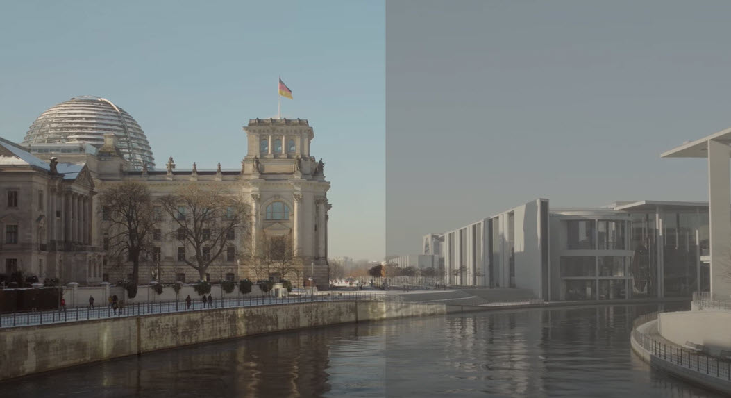
Another way LUTs are used is in processing content from cameras that use different ways of capturing content. The way that the eye works is logarithmic, so to make the most of limited data streams, it makes sense to store captured video or image content and store it in a logarithmic way. Sony does this for HDR content with its S-Log 3 format (and there are plenty of other alternatives available). That uses particular tone mapping to squeeze images with a wide range into a smaller curve. However, if you view the content ‘as is’ it looks very ‘grey’ and lacking in contrast. You need to process the images through a LUT to make the images look more natural. Typically, that might be the inverse of the curve used to capture the content.
 A LUT used to process S-Log 3 camera output – right. Source: YouTube
LUTs for Creative Purposes
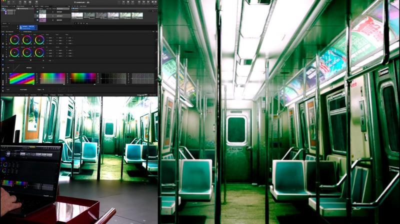
One you start to do these kinds of processes, though, you realise that while LUTs can be useful for compensating for technical differences, such as different makes and models of camera, they can also be used for a wide range of creative purposes boosting some colours or regions of brightness and reducing others. So a particular production may use a standardised LUT to give a particular ‘look’ for a certain content item. Classic examples of this are movies like “The Matrix” which has a kind of green cast that makes it very distinctive. The final colour grading is not done on set, but a LUT can be developed that gives an approximation to the likely end result and ‘LUT boxes’ can be used to process the output of raw footage to give a sense of how they will look in the final version during the filming process.
All of this came to mind because of a recent announcement by Brompton, the maker of high quality video processors for LED walls that are used in virtual set and virtual production scenarios. The firm recently added the ability to download LUTs to its video wall processors and now German software company, Pomfort has added the facility to include uploading of custom LUTs from its Livegrade Studio software, directly to the Brompton S8 and SX40 processors. This brings much more flexibility and accuracy to the virtual production. That should allow better control of the colours in the backgrounds of LED volumes to optimise the workflow and colour quality. Although final grading is still likely to be done in post production, the move should allow the content to be captured more closely to the final intended look.
For more on some of the colour issues related to RGB LED volumes for virtual production see RGB is Not Enough for Virtual Production. (BR)
 Brompton Technology Colour Management – Click for higher resolution
Thanks to Brompton for moving this article outside the Display Daily paywall so that it won’t count as one of your two free articles if you are not a paying subscriber.

