Our own Peter Palomaki tore down a Samsung S95B QD-OLED TV. Teasingly, in this part one video, he showed that he would be using a UV flashlight – a test we had hoped to try on the Nanosys booth at Display Week, but hasn’t, so far disclosed the result.

There has been discussion of the steps that Samsung has had to take with this wider colour gamut display to make it more accurate to the DCI-P3 gamut than it would be if the primaries were at the limits of the quantum dots’ output. As Palomaki found, a ‘pure’ red test signal showed a tiny amount of green and in blue a little bit of red. In green, there was an inclusion of some red. All the ‘pure’ colours were diluted. He explained some of this in his article last week. (Give me back my gamut, QD-OLED!)
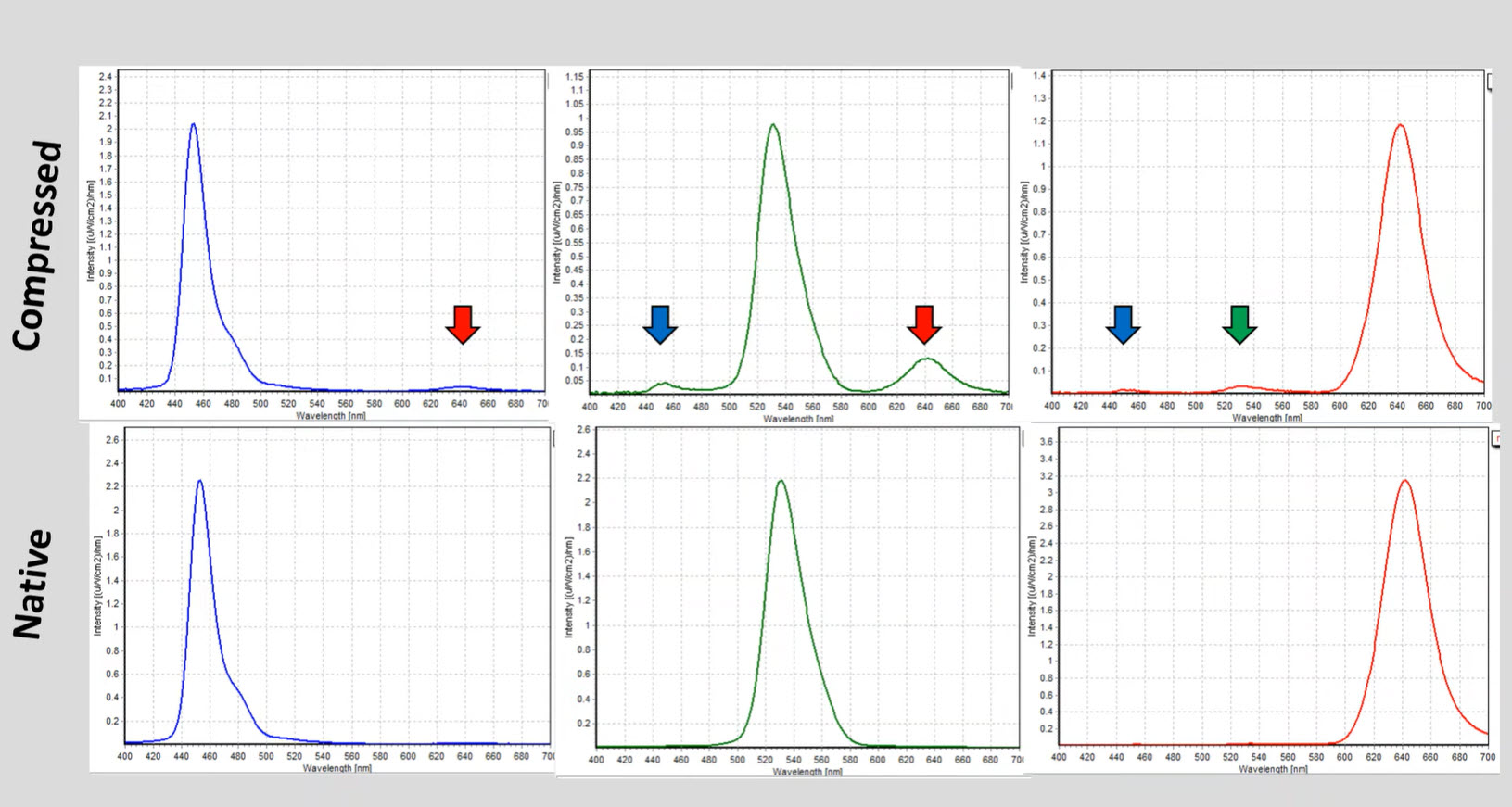
He also tested a small ‘thumbnail’ patch of the display and in green with a small area, and in this case there is no red – it is just a pure green. This suggests that there is a ‘compression’ effect on the chromaticity range from the electronics in the set when the video processing kicks in. The compression restricts the range to DCI-P3.
Set Makers Have to Make Tough Choices
For set makers, there are real choices to be made when the display can exceed the chromaticity range (often called the gamut) of the content available.
One strategy is to clip the colour. That is to say, if a colour is outside the range of the content (Rec.709 or DCI-P3 for example) then you simply show the colour within that range that is as close as possible to the edge of the colour triangle that is still within the standard. The advantage of this approach is that you can keep all the colours within the range as accurate as possible. If the colour grader or the master viewer of the content also used clipping to limit the range seen, you will be as close to the ‘creative intent’ of the colourist or broadcaster as you can get.
However, if the person finalising the quality of the colour was using a display with wider capabilities in terms of chromaticity or colour volume, then, if you clip, you will lose some detail that was viewable at that time. In this case, it may be better to still show some gradation of the image in the areas that are outside the range of the display. To do that, you have to accept some inaccuracy in the grey scale response of the display.
If you don’t know what kind of display the image was mastered with, it can be a difficult decision as to how to proceed. That’s where metadata comes in. With SDR content, which is mastered at low levels of luminance (typically 100 cd/m²) and typically in a Rec. 709 limited chromaticity range, you don’t use metadata. However, in HDR, content might well have been mastered on a set with 1,000 cd/m² of output (and in the case of Netflix, a grading monitor with at least 1,000 cd/m² is mandatory). There are grading monitors with 4,000 cd/m² of output and, in theory, up to 10,000 cd/m² could be used with the PQ curve.
Metadata is available in HDR10, HDR10+ and Dolby Vision HDR content, although it’s not used in HLG. In fact, the reluctance of broadcasters to accept a system with metadata after some unhappy experiences with audio and metadata was one of the driving factors behind the development of HLG. In HDR10, a single set of metadata about the mastering conditions is given along with the content to allow the set to make ‘more intelligent’ decisions about how to process the signal. In HDR10+ and Dolby Vision, metadata can be sent on a frame-by-frame basis to allow even finer control.
Samsung has added another layer of control with its HDR10+ Adaptive which takes into account data on the viewing environment in the home to take into account how the viewer’s eyes may be reacting differently in different ambient lighting.
As we reported in 2020, Nanosys has done some great work to show that even in content that is ostensibly limited to DCI-P3, there can be significant colour data outside the range, so this is a complex area. (So, There’s no Colour Content above P3 Gamut, is There? (Part 1))
If you are interested in a deeper dive into colour gamut mapping. Samsung Electronics’ LSI division published a paper during Display Week (52.5) on how it developed a technique for production line mapping of mobile OLED displays to a standard gamut.
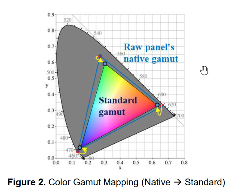 Image from Samsung’s Display Week Paper
Anyway, back to the Teardown!
When Palomaki got to the teardown itself, he tried to keep the display functional as long as possible although it did get cracked. The metal back of the set and the ‘bezel around the edge were glued onto the display. Palomaki found a layer below the OLED itself that he surmised is a heat conducting layer to help to cool the OLED. The layer was removed but the display itself was broken in the process.
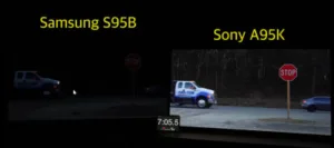
Other reviewers that have compared the Samsung with Sony’s QD-OLED sets and found that the Sony has a metal heat sink to help limit the rise in temperature in bright areas of the display. Temperature rises are associated with image sticking in OLED TVs and HDTVTest’s Vincent Teoh has shown how the use of a heat sink allows Sony to have less extreme control of the display luminance to avoid potential burn-in and sticking issues. As far as I am aware, the first use of a metal heat sink like this in a commercial product was by Panasonic.
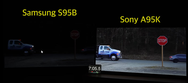 After seven minutes of this image, Teoh found that the Samsung set aggressively darkened the display, while the Sony, with its heatsink, did not. The auto-dimming could be switched but this could invalidate the warranty on burn-in issues. Image:HDTVTest video capture.
And Back Again..
Anyway, removing the heatsink got Palomaki to the OLED layer and the QDs themselves (which are in separate layer. And there we come to a … Palomaki is promising a second video where he digs more into the QDs and the OLED emitter itself. I’m looking forward to it!
In particular, I’m watching for the effect of the UV lamp. At Display Week, we had fun with a Samsung QD-OLED set by using the LED on a smartphone to reduce the contrast and saturation of the panel. The bright light from the LED caused some excitation of the QDs, but it was hard to see how much of the effect was just glare from the LED. Using a UV lamp minimises the visible light so it should be possible to see the effect of light from the front of the set on contrast. (BR)