See-through light field displays are a possible building block for the next generation of augmented reality devices. There is, however, one standout problem associated with large size, see-through light field displays: the need for collimation optics.

First, a few words of background information.
There are a variety of approaches to implementing a see-through light field display. One promising candidate has been a system based on a projector and a micromirror array. The advantages of a projector-based see-thorough light field display system include:
- The ability to produce a large image with a smaller display source.
- Easy implementation of spatial / temporal multiplexing.
The disadvantages of this approach derive from the fact that the optical axes of all the micromirrors in the array are usually made to be parallel. There are several reasons for parallelism including the fact that it simplifies micromirror fabrication. The point to note is that a see-through light field display system designed with parallel micromirrors requires that the light beam from the projector be collimated and, thus, aligned with an optical axis of each individual micromirror. The use of collimation optics, however, gives rise to two issues that make it difficult to use the technology in commercial AR products:
- The volume, weight and optical path length needed for the collimation optics makes it difficult to produce a display system with a favorable form factor.
- Use of the maximum display area of the projector and the full size of the micromirror array requires an increase in the aperture size of the collimation optics.
Means to address this issue were undertaken by a team of researchers at the National Institute of Information and Communications Technology (Tokyo, Japan) led by Boaz Jessie Jackin. A recent article on this topic by the team is entitled “Digitally designed holographic optical element for light field displays.” It was published in the journal Optics Letters, Vol. 43, Issue 15, pp. 3738-3741 (2018). A copy of the article can be downloaded here.
The means investigated by the team was based on a new method to fabricate holographic, concave micromirror array sheets. The idea was to embody the function of the collimation optics directly within the micromirror array.
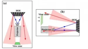
The situation is explained by paraphrasing the technical article and with reference to the figures below. In the figure, (a) shows the top view and (b) shows the side view of a typical projection-based light field display system. The blue lines show incident light and the red lines show diffracted light when no collimation optics is used. As shown in (c), the collimation optics helps in collimating the diverging projection beam, thereby bringing the diffracted reconstruction beam back into the viewing zone. The researchers describe means to replace the collimation optics through modifications to the micromirror array as shown in (d) and (e). The modification is a simple, variable tilt function added to all the holographic micromirror elements in the array both in the horizontal and vertical directions. By these means, the principle rays at the extreme edges are brought back into the viewing zone.
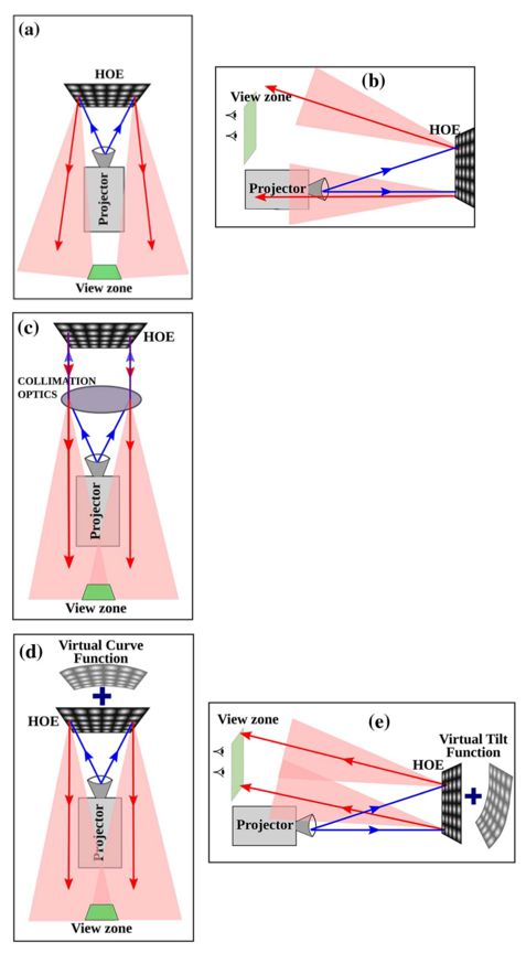 Principal ray direction without collimation optics: (a) top view and (b) side view. Principal ray direction with collimation optics: (c) top view. Principal ray direction with virtual curve functions: (d) top view and (e) side view.
Producing a micromirror array with the desired so-called “virtual curve functions” required development of a novel fabrication process. The researchers call their newly developed micromirror array a Digitally Designed Holographic Optical Element (DDHOE).
An innovative micromirror array fabrication process proposed by the researchers is based on holography and used a Spatial Light Modulator (SLM) to generate the object beam in the production of the DDHOE. By this means the micromirror and the required horizontal and vertical tilt functions were included in the DDHOE. The SLM allowed the researchers the freedom to choose from a variety and combination of parameters to implement a wide range of DDHOE optical properties. Using the new fabrication method, the researchers note that it took 16 hours to fabricate a 10 X 10?cm micromirror array but that the function of the collimation optics could indeed be replaced with the horizontal and vertical tilt functions included in the micromirror array. As a result, the display system could be significantly simplified.
The first step in the design and implementation of the new micromirror fabrication method was to numerically compute the hologram data. This data was then fed into the SLM that was used to generate the object beam that embodied the concave mirror as well as the horizontal and vertical tilt functions.
The team’s article presents information on the calculation needed to compute the hologram. The article also presents detailed information on measurements made on prototype devices as well as the test results.
The bottom line of the test results is that the researchers achieved 3D light field reconstructions having a size of 20?cm X 10?cm and 6 cm in depth. This was accomplished with a conventional projector – without any collimation optics.
Also in their article, the researchers offer comments on limitations found with the new fabrication method. These included the choice of focal length and maximum concave mirror tilt which were found to be limited by the space bandwidth of the SLM. They go on to explain that currently available SLMs allow the realization of display systems up to 20 cm with a view angle of 10º.
In the future, the team “intends to conduct a quantitative study to determine the maximum depth of field and resolution of the reported system and to improve the fabrication technique to accommodate color reconstructions and larger view angles.” -Arthur Berman
National Institute of Information and Communications Technology, Boaz Jessie Jackin, [email protected]