On December 1st, I had a chance to attend a lecture given by Professor Kyung Cheol Choi at the Center for Advanced Flexible Display Convergence in the Korea Advanced Institute of Science and Technology (KAIST). Dr. Choi is also the Director of the LG Display – KAIST Cooperation Center.
Dr. Choi at Columbia University
The lecture was titled “Design of Flexible OLEDs and Wearable Displays” and was targeted at graduate and upper-level undergraduate Columbia University electrical engineering students studying displays. Steve Sechrist recently wrote a Display Daily about flexible OLED displays at KAIST, but Dr. Choi went into considerably more detail in his talk, enough to justify a follow-up article.
According to Dr. Choi, virtually any flat panel technology can be made into a flexible display. Ones he mentioned included TFT LCDs, OLEDs, LEDs, Els, PDPs and EPDs. For many of these technologies, a flexible display today means putting multiple very small non-flexible displays on a flexible substrate. For example, there are many flexible LED displays for the rental and staging market where individual RGB LEDs are fastened to large, flexible and sometimes transparent substrates.
He has chosen to focus his group on flexible OLED displays because he says they have a variety of advantages over the other technologies. Other than e-paper displays (EPD), flexible OLEDs have the most mature technology as true flexible displays, rather than small rigid displays on a flexible backing. OLEDs also have far better color than any of the existing EPDs, flexible or non-flexible. As emissive displays, they can also be used in many applications not suited for EPDs.
 Examples of existing flexible OLED Displays given by Dr. Choi.
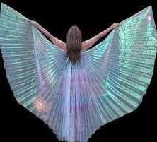
In the future, wearable OLED displays may become a part of high fashion.
Dr. Choi said that fully flexible displays, for example displays printed onto fabrics to be used in clothing, are the worst-case for flexing and the reduction of OLED lifetime. Crumpling cloth is a particularly bad case of flexing the display. However, applications that require this full-flexibility are the ones he and his colleagues are targeting. For maximum life and flexibility, no breakable materials should be used in the stack forming the OLED display. Unfortunately, two common materials used in OLED displays are considered breakable: the indium-tin oxide (ITO) transparent conductor and the multi-layer encapsulation barrier.
 DMD transparent electrode used by KAIST
There are multiple technologies under development that can replace ITO with non-breakable transparent coatings. Ones Dr. Choi mentioned included carbon nanotubes and graphene; metal grids; conducting polymers; and dielectric–metal–dielectric (DMD)/organic-metal-organic (OMO) technologies. The technology his lab is working to develop is DMD, with silver (Ag) as the metal, as shown in the figure. The figure makes these electrodes look easy to manufacture but, according to Dr. Choi, they are not. In particular, for a silver film to be transparent, it must be very thin and it is difficult to make very thin silver films because silver tends to have non-continuous, island-like growth properties. Nevertheless, his lab has achieved satisfactory sheet resistance and flexibility using a 7nm silver film and using glass as the inner dielectric and ZnS as the outer dielectric layer.

Encapsulation of OLEDs is needed because water vapor and oxygen cause non-emissive dark spots in OLED. With continued exposure, these dark spots grow, merge and render the OLED useless. While TFTs and LCD materials are also vulnerable to oxygen and water vapor, Dr. Choi said OLED materials were about 10,000x more vulnerable than TFTs and 100,000x more vulnerable than LCD materials. This means OLEDs need advanced barrier technologies not needed for other flexible display technologies such as LCDs or EPDs.
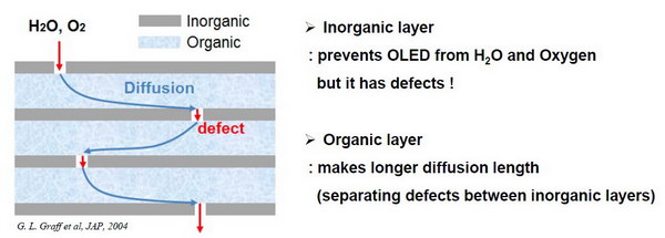 Schematic design of a multi-layer oxygen and water barrier for a flexible OLED.
The design of the normal barrier layer used in flexible OLED displays is shown in the figure. Note that if it were possible to make a “Perfect” inorganic layer, one that remained perfect with flexing, the multi-layer structure would not be needed. This multilayer structure will slow down the penetration of water and oxygen to the OLED layer to acceptable rates, but does not stop it completely, limiting the lifetime of all current flexible OLEDs. With flexing, these inorganic layers tend to crack, increasing the defect density and reducing the lifetime of the OLED further. With extreme flexing, such as an OLED display on fabric might see, this reduction in life might become unacceptable. Dr. Choi showed photos of a nominally flexible OLED display destroyed after a single flex similar to what a display on fabric would see.
Dr. Choi and his group are approaching this problem from two directions. First, the use of advanced materials, in particular using a S-H (silica/PVDF-HFP [poly(vinylidene fluoride-hexafluoropropylene)]) nanocomposite material as the diffusion layer and Al2O3 as the inorganic layer.
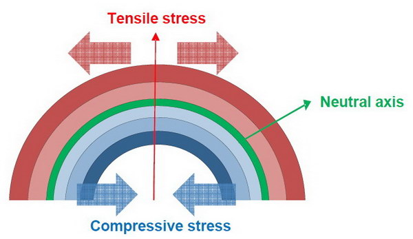 Stress and the neutral axis in a flexible structure
These advanced materials don’t solve the problem completely so Dr. Choi’s group is using a technique known as “neutral axis engineering.” In any flexible structure, when it is flexed, the outer layers experience tensile stress (i.e. the materials are stretched) and the inner layers experience compressive stress. There is some axis inside the material where there is neither tensile nor compressive stress, although the materials are still bent. If a composite structure is designed so the most vulnerable material that is part of the structure is placed at the neutral axis, the material is least likely to be damaged by flexing the composite.
For a flexible OLED, the most vulnerable material in the structure to damage from compressive or tensile stress is the relatively brittle S-H nanocomposite/Al2O3 barrier layer. By designing the OLED stack to place the neutral axis at the center of the barrier layer, stress on this layer is minimized, damage to the layer is minimized and lifetime of the OLED is maximized. Unfortunately, in the typical flexible OLED display this is not possible because there are two barrier layers, not one. If the neutral axis is placed on one barrier layer, the other barrier layer is far from the neutral axis and is likely to fail on flexing.
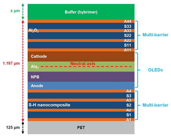 Positioning of the neutral axis using a buffer layer in a flexible OLED display
Position of the neutral axis can be controlled by putting a buffer layer on the outside of the stack. This buffer layer is not needed for the operation of the OLED stack, it is only used to control the neutral axis position and improve lifetime. If only a single barrier layer is used, as in an OLED display made on a flexible but impermeable metal substrate, the buffer layer would be designed to put the neutral axis in the middle of the one barrier layer. In the more normal case where two barrier layers are used as shown in the image, the best that can be done is put the neutral axis half-way between them. There will, of course, be residual stress on both barrier layers on flexing, but this stress is minimized.
Once a long-life, fully flexible OLED technology is developed, there are two approaches possible to the types of OLED on fabric displays Dr. Choi’s lab is striving for: putting the OLED display on the finished fabric or putting the OLED on the fiber before weaving the fiber into a fabric. At this point, the first approach is probably closest to production since it involves making a more or less conventional flexible OLED display (the more flexible the better) and then bonding it to the fabric.
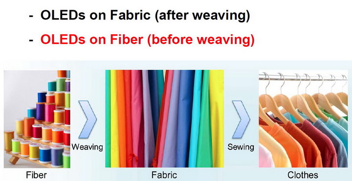
While it is still much more of a research issue, putting the OLED on the fiber before the fiber is woven into a fabric or made into clothes has intriguing possibilities and, perhaps, some technical advantages. The possible technical advantage is that since individual fibers in cloth can move relative to each other, the stress on the individual fibers and any OLED materials and structures on these fibers is minimized and therefore there would be fewer stress-induced lifetime problems. If the OLED on a single fiber is damaged to the point where it no longer emits light, this is likely to have minimal effect on the overall performance of the fabric due to the redundancy of multiple fibers in the fabric.
If OLED displays are made on more-or-less conventional substrates and then bonded to the finished fabric, this advantage of motion between the fibers is lost. In addition, the fabric will now drape differently and have noticeably less flexibility.
OLED on fiber will require new manufacturing techniques. On conventional substrates, materials can be spin coated or evaporated onto the substrate and even ink jet printed. On the original fibers, the materials will probably need to be dip coated. Both individual fiber and roll-to-roll processing techniques are possible, as shown in the image.
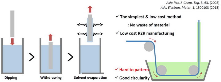 Individual fiber and roll-to-roll manufacturing of OLEDs on fibers
In addition to the manufacturing problems, OLED on fiber displays have additional problems that will need to be addressed before they can be used in production. One of the key issues is powering and addressing the individual fibers.
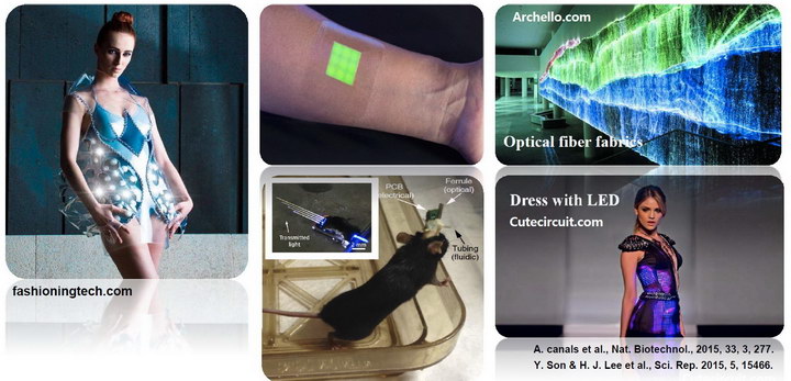 Potential applications of OLEDs on fabric and fiber. Note that the pictured applications are currently mostly done with LEDs and optical fibers, not OLEDs.
The obvious applications of OLED on fabric, whether the OLEDs are on the fibers or bonded to the fabric after weaving, are in fashion, architecture and the decorative arts. According to Dr. Choi, there are additional, more practical applications such as healthcare and opto-genetics. Some of these applications like opto-genetics can only be done by OLED on fiber, where only a single fiber is needed. Perhaps none of these applications are near-term but, like I said before, they are all intriguing. –Matthew Brennesholtz

