For nearly a hundred years after Friedrich Reinitzer observed cholesteryl benzoate changing into its liquid crystal state in 1888, nine years before the invention of the CRT, liquid crystals remained little more than a chemical curiosity. Then in 1971, Drs. Schadt and Helfrich of Roche developed the twisted nematic liquid crystal and opened the door to the first commercial use of LCs.
The dictionary defines nematic as: “Existing in or having a mesomorphic state in which a linear orientation of the molecules causes anisotropic properties”. Mesomorphic means a state between liquid and solid, which applies to liquid crystals. In anisotropic filtering, anisotropic is defined as “non-uniform shape”. In chemistry, the word has a slightly different meaning and is used to describe substances that have different physical properties in different directions. So a nematic liquid crystal is one that has different physical properties in different directions because the molecules are arranged in a line or chain.
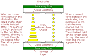
To make a monochrome TNLCD, a glass panel, or substrate, is coated with a transparent layer of metal oxide which will be used as an electrode. A thin layer of polymer is then applied to the substrate and the substrate is rubbed in one direction with a cloth, causing microscopic grooves to be formed in the polymer. A second substrate, also with rubbed polymer layer, is then laid on top of the first, with tiny spacers between the two keeping them an exact distance apart. The edges of this sandwich are then sealed, apart from a small gap at one corner, and the space between them is evacuated to form a vacuum. The TNLC is injected between the substrates, the corner of the sandwich is sealed and polarising filters attached to both substrates. These are aligned at right angles to each other, with each one aligned with the grooves in the substrate’s polymer layer. The rod-shaped molecules at each surface align parallel to surface in the direction of the grooves. Because the molecule stack twists through 90°, the surfaces of the stacks are now aligned with the axes in the polarising filters on the outside of each substrate.
When light is shone on the sandwich, the polarising filter blocks all light except that which is vibrating in a single plane. This light then passes through the lower glass substrate, its metal oxide electrode and polymer layers and enters the liquid crystal layer. Here, its plane of vibration is rotated through 90° as it follows the twist in the LC stack. It then passes through the layers of the second substrate and arrives at the second polarising filter (known as the analyser) with its plane of vibration aligned correctly to allow it to pass through the filter. When a voltage is applied to the electrodes, however, the molecules in the LC chains react by changing orientation until they are aligned perpendicular to the substrates, destroying the twist. The polarised light now passes through the LC without its plane being rotated and it arrives at the analyser oriented at right angles to the filter’s plane of polarisation and, consequently, cannot pass through it.
TNLCDs were the first liquid crystal displays to be produced and, as is often the case in early developments, have shortcomings, e.g. a low contrast ratio, narrow viewing angle and slow response time. They are relatively cheap to produce, though, and are adequate for such applications as calculator and watch displays. The next stage in LCD development is the STNLCD.
Update: TN LCDs with active matrix backplanes have improved in performance considerably over recent years. Efficiency is relatively high, new viewing angle films have improved the performance and improved driving schemes have speeded up response times. As a result, nearly all notebook and monitor LCDs up to 19″ are made using TN technology at the time of writing (July 2006).

