Quantum Dots (QDs) were again a hot topic at Display Week. I attended over two dozen talks with a focus on QDs, and many more where QDs were a secondary topic in the conversation (and that doesn’t even include the posters). Topics ranged from the fundamentals of InP surface chemistry, to new film morphologies aimed at enabling super thin and narrow bezel displays with QDs, as well as a half day of talks focused solely on electroluminescent devices (what many see as the ultimate display technology). What follows is my attempt to summarize the (highly) technical talks and provide some commentary on the trends I saw emerging this year. I’ll give you my takeaways right here up front, but please read on for more detail, there was a lot of technical progress to write about this year!
Takeaways from SID 2018 relevant to the quantum dot industry:
- Perovskite QDs are gaining momentum
- QD Film has matured, but continues to advance
- QDs as color filter replacements are making progress but with many technical challenges
- Ink Jet printing is feasible for many QD applications
- Electroluminescent displays architecture is coming along, but stability has a long way to go
- Competition in wide color gamut includes more than just QDs
I have split up my summaries into the following sections. Keep in mind many of the talks covered topics across many sections, but I did my best to categorize them according to their main focus/application.
QD Introductory Talks
- Indium Phosphide (and other non-Cd materials)
- High Stability QDs and Phosphors for on-chip
- Non-QD technologies for wide color gamut
- Quantum Rods
- Perovskites
- QD Film
- Printing and Patterning
- Electroluminescent QD advancements
Commonly used acronyms:
QY = Quantum Yield – assessment of the efficiency of QDs (the higher the better, ideally 100%)
FWHM = Full Width at Half Maximum – measurement of the width of QD emission peak (narrow = better)
PL = Photoluminescence (QDs operating as optical down-converters)
EL = Electroluminescent (QDs operating as electrically driven light engines)
QD Introductory Talks
S-1: Fundamentals of Quantum Dots and Their Application to Displays:
This year there was a short-course (if you can call 4 hours “short!”) dedicated solely to the topic of QDs in displays. Professors Yajie Dong (University of Central Florida) and Xiao Wei Sun (Southern University of Science and Technology) tag-teamed the event and provided a great overview of the fundamentals of quantum dot chemistry, photophysics, and implementation in displays now and in the future. The impressive properties of perovskite QDs were a focus, but likely because that happens to be a focus area for Prof. Dong’s research group at UCF.
Two major modes of QD operation were covered
- Photoluminescence (PL) and
- Electroluminescence (EL).
PL covers any technology where blue photons are absorbed by QDs and re-emitted in red or green colors (for example film, color filter replacement, and on LED chip). EL is any device where the QDs are electrically stimulated to give off photons of blue, green, and red color. Products based on PL operation are more mature and already in the market due to advances to their stability as long as they can be properly protected from atmospheric exposure. QDs in EL operation still have years of research ahead before they become stable enough to be widely used in commercial displays. An additional challenge in EL mode is the need for blue QDs in addition to the more common red and green. Blue QDs are known to be far less stable than green and red – in part due to less intense study, so far, as they are not required in PL mode.
SE-7: Quantum-Dot Displays: Advances and Outlook:
Charlie Hotz from Nanosys presented to a standing-room-only crowd excited to hear about the future of QDs in displays. Charlie presented the Nanosys vision for the future of QDs (beyond QDEF film) which included QD Color Converter (QDCC, which most people are calling QD color filter), and electroluminescent QDs. It’s worth noting that they seem to be putting all of their focus on indium phosphide (InP) QDs rather than continuing to push the envelope with heavy metal materials that contain Cd or Pb.
There is still an exemption in place in the EU for cadmium in displays, but it is set to expire in 2019 (with a wind down period to follow) if no renewal is granted. While not all countries follow suit behind the EU, many do, which means products with >100 ppm Cd may no longer be a viable product. (and Apple and Samsung have corporate policies of not using cadmium – Man. Ed.) Nanosys continues to be a leader in the field and showed an impressive looking 65″ Vizio P-series ($2200) in their booth containing their QDs which will be available in the states soon.
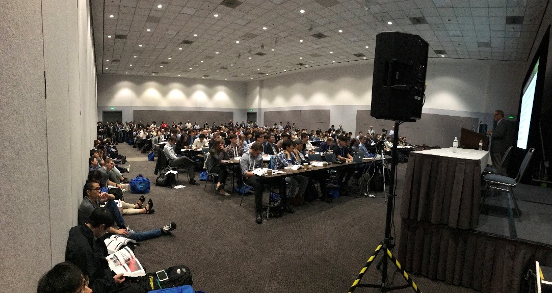 Charlie Hotz of Nanosys gave a talk to a standing/sitting-room-only crowd on Monday (Photo credit: Nanosys).
Indium Phosphide (and other non-Cd materials)
4.1 – Invited Paper: Role of Phosphorus Oxidation in Controlling the Luminescent Properties of Indium Phosphide Quantum Dots:
Brandi Cossairt educated the audience on the history of InP QDs which were first synthesized nearly 25 years ago! Her research group at the University of Washington has become expert at the surface chemistry and synthesis of InP QDs. She reviewed the two major reasons that InP QDs have lagged behind CdSe in optical properties.
- The persistence of magic-sized clusters present during the synthesis, and
- their highly sensitive surface chemistry, especially at the interface between the InP core and ZnS/Se shell. Her group uses a new method to assess phosphorus oxidation (benchtop X-ray emission spectroscopy), which may soon become the preferred way to evaluate the surface chemistry of InP QDs. There is still work to be done in InP, as it is not clear yet how the oxidation of surface P atoms impacts the properties we care about in displays, mainly QY.
4.2 – From the Synthesis of High-Quality InP-based Quantum Dots to the Development of Efficient QD Light-Emitting Diodes:
There were two separate groups from Fraunhofer (Germany) working on QDs at Display Week this year (see paper 11.5 for the other one). The focus of this paper was the ability to create InP EL devices with high performance. While still inferior to CdSe ELQD devices, the group was able to show good performance using an “inverted” device design which is well-suited for InP devices and has a number of advantages such as opening up new processing and material possibilities. With minimal optimization of QD design and device layers, efficiencies of ~5% were achieved (for comparison, CdSe ELQD devices regularly achieve ~20%). As expected, the lifetime of the devices is very short, measured in minutes. However, Fraunhofer did have a demo of both green and red InP ELQD devices in their booth on the showroom floor which ran (at low brightness) for multiple days.
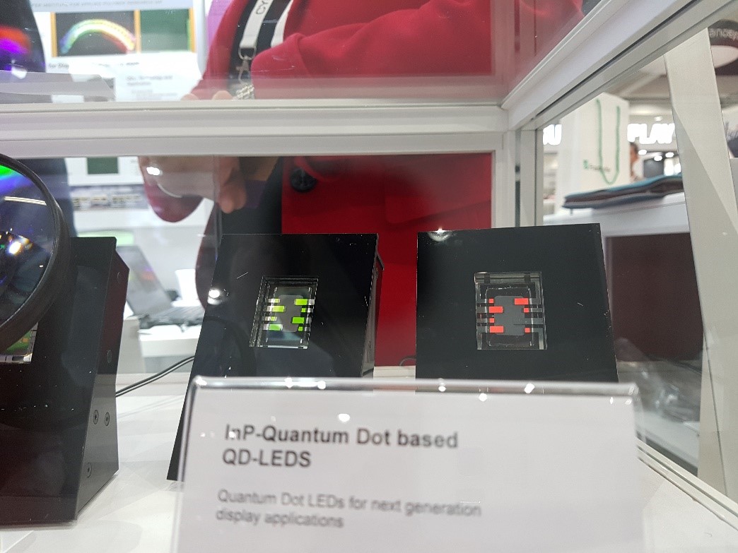 Red and green InP QLED devices shown by Fraunhofer IAP at Display Week 2018 (Photo credit Andre Gessner)
4.3 – Solution Synthesis of High-Quality Indium-Nitride Quantum Dots:
While the LED industry is built on the ability of InGaN (and other nitride alloys) to be efficient emitters, to date there have been very few reports of III-nitride QDs (InN, GaN, and alloys). Ulvac presented data that demonstrated that III-N QDs can in fact act as a down-conversion material by being excited with UV light and emitting visible photons. To my knowledge this is the first time anyone has shown data on emissive III-nitride QDs. Perhaps it’s worth mentioning here that I have studied this material in depth and published on the topic in 2012. There are few known methods to making InN QDs, and the authors tweaked know methods by borrowing from chemistry known to work well with InP and CdSe QDs to create InN QDs that emit visible light. The optical properties left something to be desired (130-200 nm FWHM), but this material is still in it’s infancy, and could be another viable option for a Cd and Pb-free QDs.
11.2 – Solution-Processed High-Performance Photodetector Based on Lead-Sulfide Quantum Dots:
The team from SUST used QDs for an application outside of the traditional topics seen at Display Week. Here they use lead sulfide QDs (which absorb well-into the infrared) to create a photodetector capable of detecting light from the visible to short-wave IR. The team used ligand exchange and a layer-by-layer approach to achieve high quality films that detect light out to ~1000 nm. I recently wrote a blog on this topic – Quantum dots do more than just emit light.
80.3 – Research on ZnO-MgO QDs and Its Application in QLEDs:
There were not many groups working on materials other than CdSe, InP, and perovskites, but Southeast University showed off their work on ZnO/MgO core shell quantum dots. In theory, this material is already oxidized so should be much more stable than other QD types. Due to the wide bandgap of ZnO, the material absorbs only UV light (<350 nm) and operates on a defect emission mechanism which means it emits in the visible spectrum range. Broad emission means this technology probably won’t be showing up any time soon in our living room.
High Stability QDs and Phosphors for on-chip
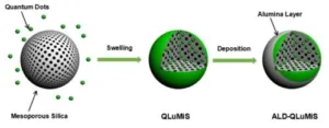
4.4 – High-Stability Green Quantum-Dot Luminescent Microspheres:
Tianjin Zhonghuan Quatnum Tech Co. presented on their technology which enables QDs to be stable at high temp and high light flux – i.e. on an LED. QDs on chip have been a very difficult technology to develop, and it has only seen success recently, but for red QDs only (See Lumileds paper 32.1). To date no one has been successful in developing a green QD down-converter capable of surviving on-chip conditions. In this paper the authors describe a method to improve stability by using atomic layer deposition (ALD, a gas phase process), to encapsulate QDs embedded in a porous silica microparticle. The result is improved lifetime, but at the cost of lower quantum yield. This approach shows that improving green QD performance on an LED is possible, but there is still work required before it is stable enough for long term use.
Cartoon process for incorporating QDs in porous silica and encapsulation with alumina
32.1 – On-Chip Red Quantum Dots in White LEDs for General Illumination:
The team at Lumileds reviewed their first-ever QD on-chip product that was published last year. The red QD solution provides enhanced efficacy and color quality for lighting products. While stability has traditionally been a problem for QDs, Lumileds has made it work through collaborative efforts and by tuning their phosphor composition to balance reliability, color, efficacy, cost, and cadmium regulations. They made it clear that so far QDs so far only work well in mid-power LED packages, but they are working to improve the stability in high power and chip-on-board packages. One of the major challenges is preventing QY loss at high temp, which QDs are well-known to do. To date all QDs used in their products are cadmium based. For a more in-depth blog about their technology refer here.
32.3 – GE RadiantRed Technology & TriGain Phosphors for Wide Color Gamut Displays & Lighting:
GE has made quite a splash in the display world with their KSF/PFS phosphor technology (referred to as TriGain) (There’s More than One Way to Make a WCG LCD). GE has taken a licensing approach for this technology in the display market, while holding it close to the chest for their own lighting products. Through continuous enhancements to reliability, the GE team has created a product that is suitable for use in low to mid-power packages (<25W/cm²), but at high power the material has trouble with saturation due to it’s relatively long response time (9 µs). In some cases, the material is mixed with other red phosphors to reduce the decay time, but not without the penalty of a brightness hit.
Despite the drawback of decay time, the material has seen significant adoption in wide color gamut displays with over 20 billion (yes, with a B) LEDs containing KSF sold to the display industry (from phones to TVs). The material has an absorption spectrum that is well-matched with the blue from an LED, and six very narrow emission peaks in the red. This is clearly a competitive technology for QDs, although only in the red at this time (although GE alluded to current work on green).
Non-QD technologies for wide color gamut
71.1 – A Color Conversion Film with High Quantum Yield and Operational Stability:
Not surprisingly, LG presented an alternative way to achieve wide color gamut without the use of QDs (see discussion about LGs NanoCell technology here). In this paper they demonstrate the use of molecular dyes (this time fluorescent dyes, not just absorbers) embedded in a polymer matrix to create a down-converting film similar to a QD film (but without QDs or barrier layers). Red and green dyes with attractive properties (FWHM = 20-25 for green, 30-40 for red) have been developed specifically for this application. LG claims higher brightness with the same gamut as QDs with an optimized filter set, but it was clear, based on a question from the audience, that stability was a concern, although LG has tested in a 1000 cd/m² blue backlit display for 5k hours with less than 5% luminance drop. No word on color shift through that test, though.
71.3 – A New Solution for LCD to Achieve More than 90 Percent BT.2020 Without Quantum Dots:
This was another paper attempting to achieve wide color gamut without QDs (an emerging trend?). Here, China Star presented their methods for using optical filtering to achieve >90% Rec2020 gamut. They used small lenses over each individual LED to collimate the light followed by passing through optical filter technology consisting of >100 layers which removes the photons in between the desired primary colors. I suspect the efficiency of this approach is inferior to QDs or other fluorescent approaches, as this technology is simply removing photons, not converting them to the desired wavelengths. An interesting approach nonetheless.
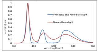 Spectrum with and without China Star’s filtering technology.
71.4 – New LCD with 97.3 Percent Rec. 2020 Color Gamut:
In this theoretical paper from UCF, the authors describe the wide color gamut limits associated with current technology (mainly due to color filters). The group tried implementing a functional reflective polarizer and a patterned half-wave plate prior to the color filters which eliminates cross-talk between neighboring spectral regions. The result – a theoretical gamut approaching Rec 2020 (97.3% to be exact) which, in reality, is probably good enough to be within the limits of human perception. We’re getting closer to “perfect,” for now.
Quantum Rods
11.4 – Novel Switching Display using RGB Quantum Rods for Wide Color Gamut:
Quantum rods represent a unique way to impart additional functionality to QDs. The team at LGD have demonstrated the use of CdSe/CdS quantum rods as a switchable material that can be selectively turned on or off based on an applied electric field. The working concept requires that the rods be aligned, which they showed to be possible also by using an electric field. If this technology can be matured to commercial viability, then it has the potential to replace the LCD liquid crystal layer, color filter, and polarizers all in one shot. But there is still a lot more work to be done as the effectiveness of blue material is poor, and performance of all colors is <50% QY.
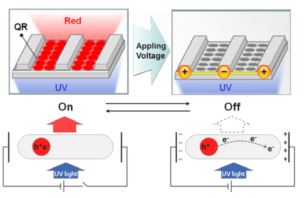 Operating principle for quantum rod display. The emission can be turned off by applying an electric field to separate the electron-hole pair.
11.5 Quantum Rods – Smart Choice for Future Display Generations:
The other Fraunhofer talk came from the company formerly known as CAN (Center for Advanced Nanomaterials), now part of Fraunhofer. This group focuses on flow synthesis of QDs, and has achieved very stable CdSe/CdS rods which show polarized emission. The quantum rods show good stability under high temp/high humidity testing, and can even be extruded at 250ºC in air with no loss in QY. If a Cd-free version of this material can be realized, I think it could have a major impact on the display industry.
64.3 – Photoaligned Quantum-Rod Films with Inkjet Printing:
Films with aligned quantum rods could be useful as a polarized emitter to enhance the efficiency of an LCD. The HKUST team showed a method of aligning quantum rods by using a polarizable molecular species (liquid crystal monomers) doped into the QD matrix. When photo-excited, the quantum rods became aligned with assistance from the molecular species. Once cured, the quantum rods remain aligned in plane of the film and achieve an impressive 0.76 polarization efficiency. When layering quantum rod colors to reduce reabsorption (red then green in optical path) they can in theory enhance the efficiency of the LCD from <5% to about 8%, mainly by providing (mostly) polarized light to the first polarizer, resulting in better photon usage. The only known issue so far is that the polarization efficiency decrease with increasing rod concentration, so the films that were created were fairly dilute/thin, and the devices showed only 90 cd/m² brightness.
Perovskites
11.1 – Bright Organic–Inorganic Perovskite Quantum Dots Fabricated with a Simple Ultrasonic Treatment: Perovskites were a clear trend this year (see my analysis section), with many groups demonstrating unique ways to make and use of these up-and-coming materials. Here the group from Fuzhou University created perovskite QDs using a room temperature process and an ultrasonic water bath. This simple method for creating QDs provide high quality (88% QY) green perovskite QDs as well as many other colors. An ELQD device with less than 1% efficiency was created to demonstrate the utility of these materials.
18.1 – Color Tunable, Flexible, and Efficient Light Emitting Diodes Composed of Metal Halide Perovskites:
Professor Rand gave an overview of perovskite technology during the Monday sessions, in addition to this talk on perovskite EL devices. But contrary to many of the talks, his focused on thin films of perovskites (which cannot technically be considered quantum dots). By tailoring the material composition, red through green emission can be realized. The Princeton group has been able to achieve up to 13% efficient devices on flexible substrates, an impressive number that is approaching CdSe efficiencies in EL devices. The reliability is, however, predictably poor.
18.2 – Ultrapure Green Light-Emitting Diodes using Colloidal Quantum Wells of Hybrid Lead Halide Perovskites:
The team from ETH has successfully made films with a reported QY of 97% (nearly perfect down-conversion efficiency) by intentionally imparting polydispersity in to the perovskite layers. In perovskites, the number of layers will, in part, determine the emissive wavelength of the material. In this approach the number of perovskite layers is intentionally mixed, but emission is still narrow due to energy transfer from the aggregated perovskite QDs down to the lowest energy (fewest layers) material. The result is a near perfect green emitter for Rec2020. They have created EL devices, and stated they have been working closely with Avantama to improve stability of their perovskite materials.
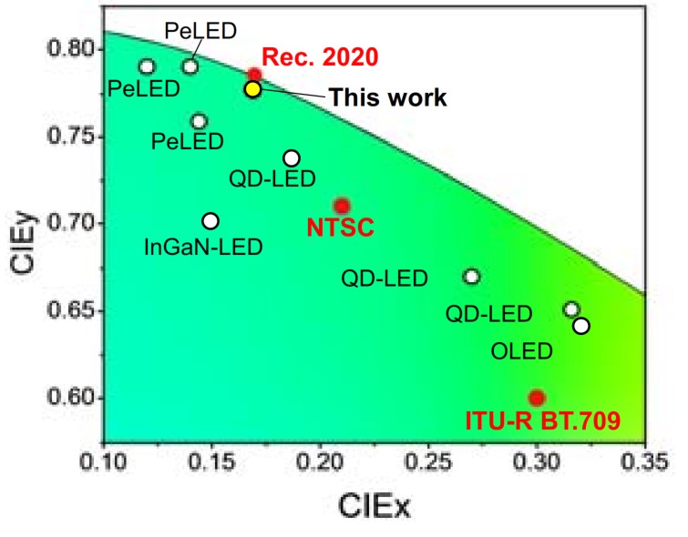 Location of chromaticity coordinates for the green perovskite EL devices made by ETH Zurich.
18.3 – Polarized Emission from Stretch-Aligned Perovskite Nanorod-Polymer Composites with High Stability:
The team from UCF has created rod-shaped perovskite particles that are microns in length by a simple one-step synthesis within a polymer matrix. Despite their rather large dimensions, the rods can be aligned by stretching the polymer, which then emits polarized light at high QY with the very narrow linewidth that has come to be expected from perovskites (18 nm). While these particles are not likely to replace current polarizers and liquid crystals due to the poor polarization efficiency, it is a unique way to create and align the rods.
18.4 – Converting Light Diffusing Polymer Powders into Stable Perovskite-Based Tunable Downconverters:
This was another paper from UCF which demonstrates the multiple ways in which you can create perovskite materials. In the paper, the group described how it created perovskite particles directly on polymer powders and found that the material had enhanced stability which could be attributed to the ability of the polymer powder to repel water, preventing exposure of the perovskite particle. While the stability is improved, it’s not clear that this method will provide the answer to the perovskite stability challenge.
41.4 – Perovskite Quantum Dots: Bringing LCD Technology to the Next Level:
Avantama presented their vision for green perovskite QDs where they are used in a film (similar to current QLED technology) but with a blue LED + KSF phosphor (to provide the red). With very narrow peaks, perovskites are extremely attractive for enhancing color gamut in the green (and blue/red depending on the color filter used). Although their perovskite materials contain lead, it is said to be under the 1000ppm limit designated by RoHS. They claim good stability to 1000 hours under wet and dry storage conditions, as well as under a flux of 100 mW/cm². Avantama is currently focused on scaling their film technology and plans to commercialize in 2019.
QD film Advancements
41.1 – QLED Auto: Quantum Dot Based Wide Color Gamut LCD-TFT Display for Automotive Applications:
In this talk Harman/Samsung laid out the future for automotive displays that use QLED technology. It’s clear that the auto industry is undergoing a transformation – analog displays are being replaced with digital displays, the autonomous vehicle is coming. With this transformation there exists an opportunity for vehicles to adopt high end displays that will create a differentiated experience. By taking advantage of existing infrastructure in Samsung’s QLED film product, Harman and Samsung have created an automotive grade QLED film (which has different requirements than a TV) which could find it’s way into vehicles in the coming years. A surprise to me was that the design cycle for this market is far longer than consumer electronics. If business is won in 2018, the product won’t find it’s way to vehicles we can buy until 2021-2022. I expect we’ll be seeing this type of display in vehicles around that time as Harman seems to have made great progress in the automotive space.
41.2 – Novel Thinnest Free Form QD Film with Honeycomb Structure:
Fujifilm presented on a new type of film structure that they have developed which could have some distinct advantages over existing film products on the market. They implemented a honeycomb internal structure fabricated by an imprint process which allows for films to be cut in any shape while maintaining low edge ingress (down to 0.2 mm). This design enables thin QD films with a total thickness of 80 um to be fabricated.
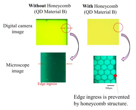 Honeycomb structure presented by Fujifilm prevents edge ingress due to atmospheric degradation.
Printing and Patterning
11.3 – Ligand Design for CdSe/ZnS/Silica Based Photolithographically Patterned Quantum Dots:
With new methods of implementing QDs in displays come new challenges. As QDs are considered as a replacement to color filter materials, or as down-converters for microLEDs, the material requirements change. One major change is that QDs must be compatible with photoresist materials such that they maintain performance and processability. The team at Tsinghua University/SUST have encapsulated QDs with a silica shell, followed by functionalization with reactive ligands to better suite the epoxy-type photoresists that are traditionally used. Using this approach, they were able to achieve QDs with a QY of 45%, and patterned them in an 8µm thick film. Additional loading or thickness will be required to achieve full blue light conversion however as the film only absorbed 30% of blue light.
41.3 – Quantum-Dot-Photoresist Solution for High-Resolution Patternable Color-Filter Films via Photolithography Processes:
Taiwan Nanocrystals demonstrated their achievements in developing photoresists embedded with QDs for use on microLEDs. In this application, the film needs to be thin (<10 µm), with high efficiency (>50%) and with high blue light abs (OD>2, >1% transmission). Giant shell cadmium-based QDs were created to reach the desired specifications with 3X enhancement in blue absorption compared to InP QDs. When loaded into photoresist at 40% loading with scattering agent, an OD of 2 was achieved with a 5µm film thickness.
41.5 – Quantum Dot Conversion Layers Through Inkjet Printing:
Nanosys and DCI recently announced a collaborative effort to create QD inks for ink jet printing. In this talk, Nanosys presented their vision for printable QDs inks for color filters replacements (what Nanosys is calling QD color conversion). QD development is being done by Nanosys, ink development by DCI. Here they used InP QDs with impressive performance (>90% QY, <40 nm FWHM) to test the ability to achieve high abs in thin films. With green QDs (known to have lower blue abs) there was still 10-30% blue light leakage, and with red QDs there was <5% leakage. With high loading come additional effects, including a wavelength shift, and narrowing of FWHM (bonus!). With these blue-like leakage numbers additional filtering is required to achieve a wide color gamut display, but Nanosys is working to improve the blue abs of their InP materials. I suspect that InP-based QD color filter technology will not be possible without the additional filters to eliminate blue light leakage and prevent ambient excitation of QDs.
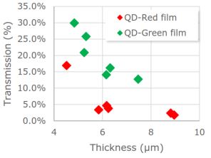 Transmission of green InP QD films still have a long way to go to reach <1% blue light leakage.
59.1 – A Full-Color Micro-Light-Emitting-Diode Display by a Lithographic-Fabricated Photoresist Mold:
The team from National Chiao Tung University presented on their use of UV microLEDs to excite blue, green, and red QDs. The QD layers were printed into photolithographically patterned wells with black sidewalls to prevent crosstalk. In this work, cadmium-based QDs were used for red and green, while ZnSe QDs were used for blue. While the device showed proof of concept that this type of display is possible, the conversion efficiency was poor (2%, 11%, 7% conversion efficiencies for blue, green, and red). The use of a bragg reflector was employed to enhance the light output by 30%. Given QDs known instability to UV light, I’m not sure we’ll be seeing a UV-driven display with QDs anytime soon.
Electroluminescent QD Advancements
While ELQD is the most immature technology of all of the QD form factors, it is still being heavily researched by both academia and industry
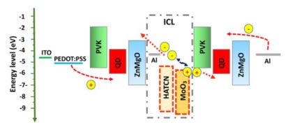
73.1 – Fully Inkjet-Printed Pixelated RGB Quantum-Dot Light-Emitting Diodes:
Fuzhou University and TCL reported on ELQD devices that were printed at all levels. This means the QD layer as well as other layers within the stack. The team used perovskite precursors to print and synthesize QDs in one step, resulting in perovskite QDs within a polymer matrix as the active layer. They also showed flexible, 4″ devices. A focus throughout the talk were the challenges associated with printing various layers such as surface wetting, coffee ring effect, and compatibility with the substrate/prior layer.
73.2 – High-Performance Quantum Dot Light Emitting Diodes and their Challenges:
Nanophotonica presented a good overview of ELQD technology and its advantages compared to other technologies. ELQD should be able to achieve a maximum of 20-25% efficiency without additional extraction layers due to the limits of light extraction, so efficiencies approaching 20% or higher are considered the maximum that one should expect to achieve. Nanophotonica has successfully built ELQD devices with >20% efficiency (green) and ~15% efficiency (red and blue). These numbers are obtained after what they call “positive aging” where the devices increase in efficiency over the first few days of testing. The lifetime of red devices is the best at thousands of hours (for T90), while the green device is measured in hundreds of hours, and blue devices are not reported (presumably only a few hours). These results are typical of the industry, and highlight the need for additional research to improve the stability of ELQD devices. They stated they are working on InP ELQD devices, and have promising results, but no data was shared.
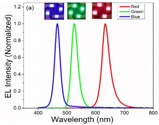 Nanophotonica’s red, green, and blue ELQD spectra.
73.3 – Full-Color Quantum-Dot Light-Emitting Diodes Patterned by Photolithography:
SUST demonstrated their AMQLED device that was patterned using traditional photoresist technology. They created cadmium-based QD-subpixels through an iterative process that caused degradation to the QDs compared to control devices made without patterning.
73.4 – Tandem Red Quantum-Dot Light-Emitting Diodes with External Quantum Efficiency over 34%:
One way to realize greater efficiency is to create tandem devices where there are two emissive layers in one device. In devices of this type the non-QD layers have a huge impact on the performance of devices. SUST presented impressive efficiencies of optimized red devices that use Cd-based QDs. One of the key features was a GaIn eutectic (liquid metal) electrode that is used in place of Aluminum.
 Structure of the tandem EL-QD device created by SUST.
80.1 – Developing AMQLED Technology for Display Applications:
Borrowing from the knowledge of AMOLED technology, AMQLED technology has advanced quite rapidly in the last few years. BOE presented a paper on their 5″ AMQLED demo built on a LTPS-TFT (low temp polycrystalline Si) backplane, as well as a 14″ demo built on IGZO-TFT (indium gallium zinc oxide) backplane. It seems that the fabrication of QLED devices is coming along nicely, but I for one am still worried about their lifetimes for the consumer market.
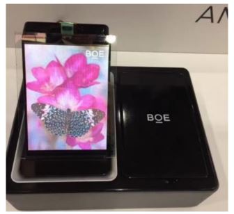 BOE AMQLED 5″ Display
 BOE’s 14″ AMQLED display
80.2 – AMQLED Display with Solution-Processed Oxide-TFT Backplane:
The focus of the team at Kyung Hee University was not on the QD layer, but rather on the cathode material. They created a solution deposition method for metal-doped zinc oxide material that showed enhanced performance over alternatives. The main reason was to obtain improved charge balance. They demonstrate a 4″ AMQLED device with green QDs based on the technology.
Summary and Analysis
There were a few topics that stood out more than others this year. Clearly the industry is interested in how to use QDs as a replacement to color filters, but it’s no easy task. For one the absorption of QDs must be very high to reduce blue light leakage, and with InP this is a very big challenge. The problem of in-cell polarizers (needed due to QDs depolarizing properties) was barely mentioned in the talks I went to, but I had many discussions with others on this topic, and it’s apparently not solved yet. If you are interested in an overview of the advantages and challenges, see a blog I wrote on this topic last year (spoiler alert: I said we might see a QD color filter display at SID 2018 and I was wrong, perhaps next year though).
Going hand-in-hand with the QD color filter application was the topic of perovskite QDs. The community is learning that these new materials could be ideal for green emitters as they have super narrow FWHM, high QY, and absorb blue light better than both CdSe and InP QDs. Some challenges include their stability (which appears to be making considerable progress), thermal quenching, and the fact that they all contain lead (another RoHS restricted material). Given these challenges, it’s not clear yet if they will find their way into consumer products, or if they will remain a research exercise. The method of implementation (for now) appears to be a film of green-only perovskite QDs with a magenta LED (Blue LED with KFS red phosphor) to achieve wide color gamut.
Patterning of QDs is becoming a focus of many companies. Future technologies like QD color filters, QDs on microLEDs, and ELQD displays will all require that QDs be patterned in some way, either by ink jet or photolithography. Photopatterning is already used in the display industry, and if QDs can enter through this avenue they may see a lower barrier to entry, but ultimately ink jet printing of QDs would be an ideal high-throughput way to pattern sub-pixels. QD’s unique property of small size and high efficiency may allow them to win out over phosphors in the long run for future applications where size matters -like micro LEDs.
Electroluminescent QD displays are still of great interest due to all of the awesome advantages they would give over LCD and OLED displays. I was impressed with the work that has been done on AMQLED displays, but clearly the focus of those talks was on the process, not the material stability. Stability remains an issue for this technology, and until that is solved, there will be only niche market acceptance. (PP)