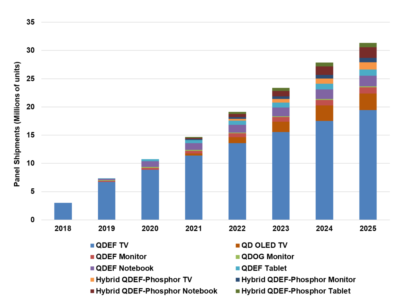
Quantum Dot-based panel shipments are forecast to grow from 3M shipments in 2018 to 31M shipments by 2025 representing a compound annual growth rate (CAGR) of 40%, according to DSCC. The report provides both technical and market information about various QD architectures for use in display including QDEF, QDOG, QD OLED, QNED and EL QDs.

There are several different types of Quantum dots (QDs) that are useful for display applications: – CdSe, InP, ZnSe, ZnTeSe and Halide Perovskites. Cadmium (Cd)-based quantum dots were historically the first type of QDs used for displays. CdSe based QDs have been shown to have high efficiencies > 90% in solution with narrow FWHM < 35 nm. However, use of Cd based QDs is regulated by the European Union’s Restriction of Hazardous Substances (RoHS) Directive for environmental toxicity forcing leading panel manufacturers such as Samsung to go Cd free for all their QLED products. Although exemptions are on-going, these restrictions saw the emergence of Cd free alternatives such as InP, ZnSe, ZnSTeSe and other novel materials such as perovskites.
InP is currently the second-best alternative to Cd QDs for red and green. Even though high efficiencies have been demonstrated, the FWHM of CdSe QDs is still better than InP; especially for green. In addition, the absorption of Cd-based QDs are higher than their InP counterparts, which is important in applications like QD color conversion/color filter. Zn-based QDs show promise for blue emission mainly for use in electroluminescent device architectures. Halide perovskites, mainly lead-based, have shown superior efficiencies and very narrow FWHMs for green and have been constantly improving in reliability. Although lead is also regulated by RoHS, the tolerance level of lead usage is an order of magnitude higher than that of Cd by weight. In summary, a lot of progress has been made in Cd-free QDs.
Premium Displays Make New Demands
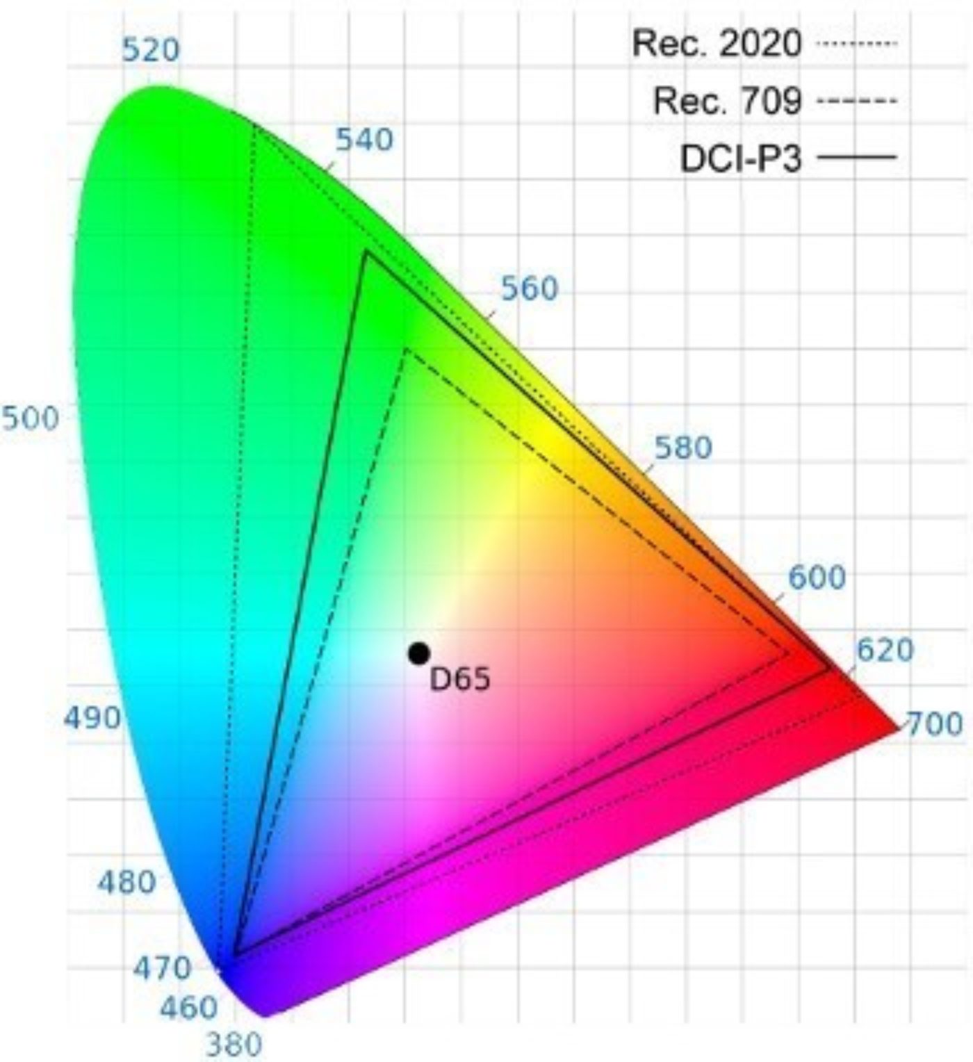
With premium displays being driven by wide color gamut and high dynamic range requirements, this segment represents a growing opportunity for QD-based displays. With respect to color gamut for UHD, for example, the UHD Alliance calls for content to be mastered in and encoded in the BT.2020 gamut with 10-bit depth and requires displays be able to process the content, but the minimum for display color reproduction was set to 90% of DCI-P3.
DCI-P3, is 26 percent larger than the sRGB / Rec.709 Gamut and is being used in UHD TVs and has been increasingly adopted in many other display applications that want to provide a wide color gamut. The BT.2020/ Rec.2020 standard is 72% larger than sRGB/Rec.709 and 37% larger than DCI-P3. Premium displays are being developed to further push the envelope of DCI-P3 and to maximize Rec.2020 coverage. Similarly, HDR requirements set forth for UHD standards include either 1000 cd/m² (nits) peak brightness with less than 0.05 nits black level or more than 540 nits peak brightness and less than 0.0005 nits black level to receive UHD Premium Certification. Premium QLED TVs deliver can deliver over 2000 nits peak brightness.
Color Gamut Comparisons
Various types of QD architectures that are currently being used or are proposed to be used in displays. These include:
- QDEF: Quantum Dot Enhancement Film (Photo enhancement/Color enhancement)
- QDOG: Quantum Dot on Glass (Photo enhancement/Color enhancement)
- QDCC: Quantum Dot Color Conversion (Photo emissive/Color Conversion)
- EL-QD: Electroluminescent Quantum Dots (Electroluminescence)
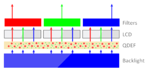
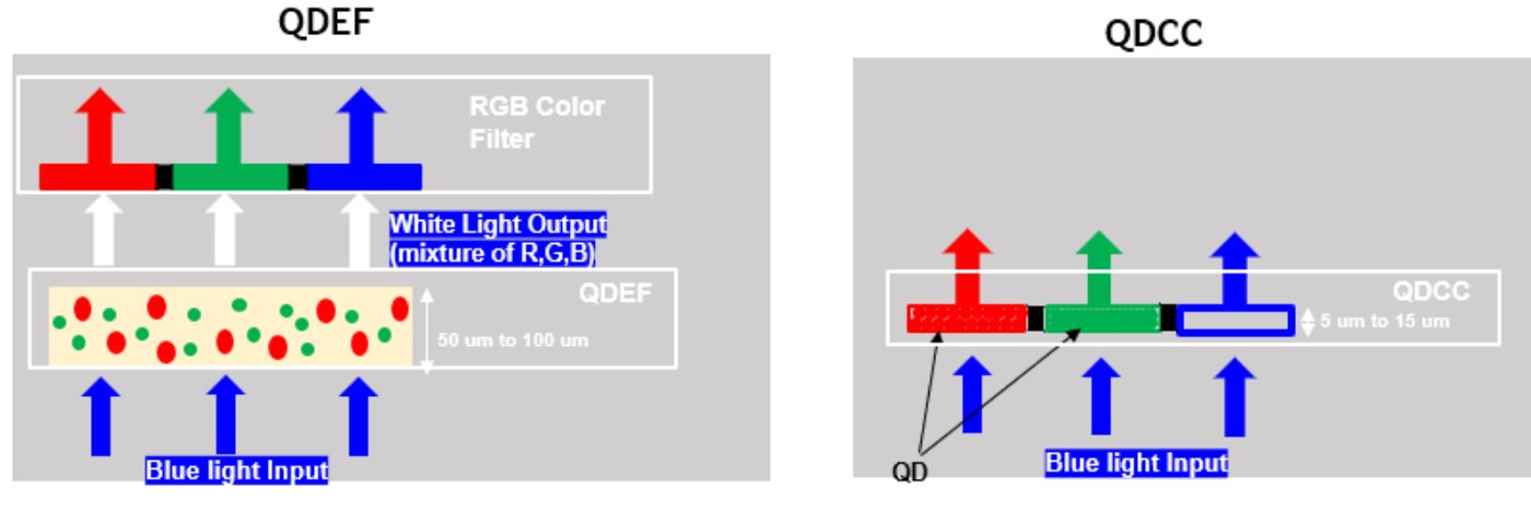
QDEF: In the QDEF architecture used in LCDs and widely marketed as “QLEDs” by Samsung, red and green QDs are embedded inside a film (QDEF). This QD film replaces the diffuser film in LCDs. The white back light unit (BLU) is replaced with a blue BLU. Blue LEDs illuminate the film, and quantum dots output spectrally pure white which is then resolved into R-G-B by color filters. The QD market in China and Taiwan is also rapidly growing with panel manufacturers and OEMs such as TCL, Hisense, Vizio, BOE, AUO and Innolux already using or planning to use QDs in their products offerings. Nanosys and NajingTech have been the leading QD material suppliers for the non-Samsung market.
QDEF Architecture in LCDs
Source: DSCC Annual Quantum Dot Display Technology and Market Outlook Report
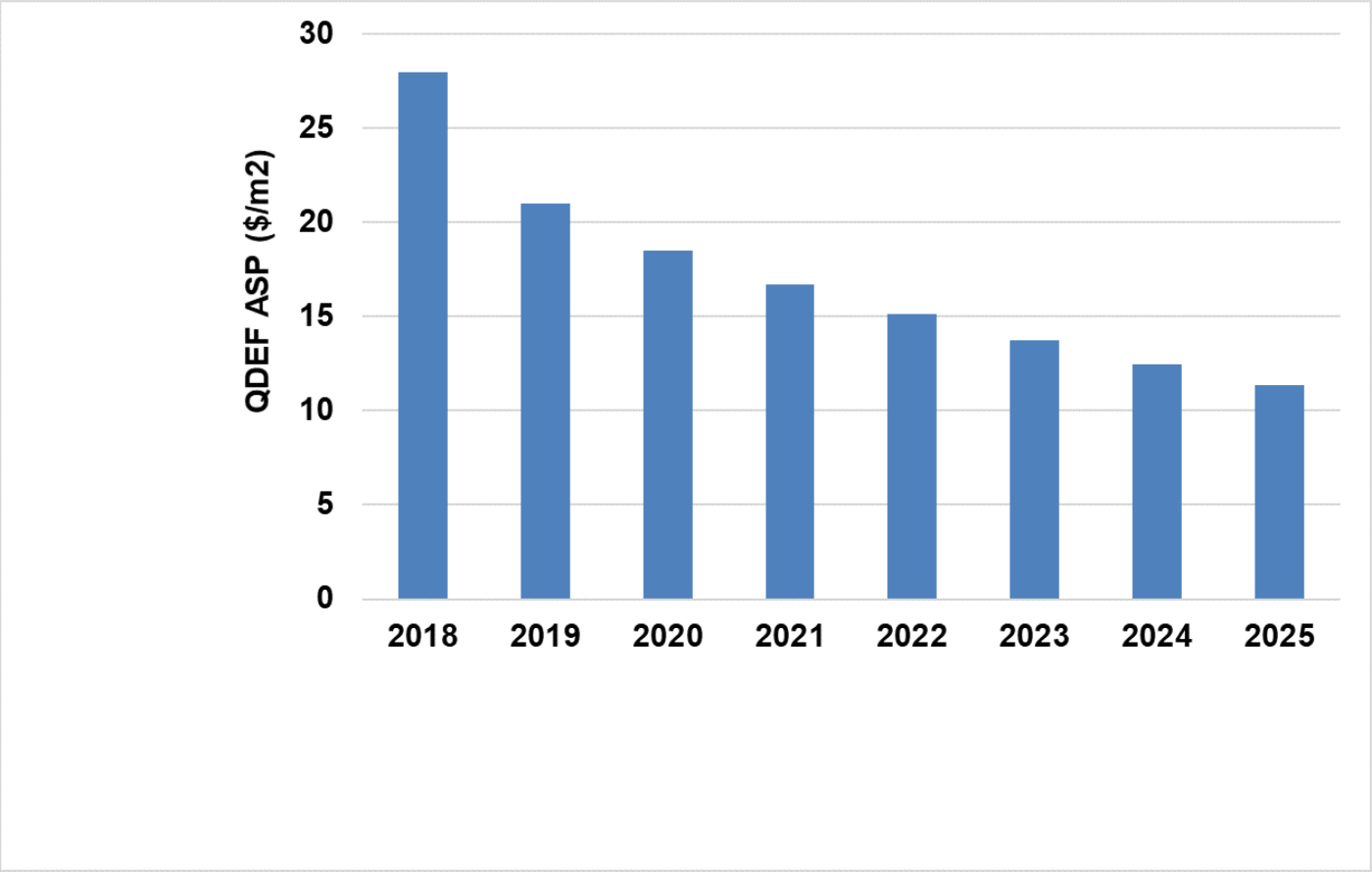
QDEF costs which have dropped rapidly over the last few years and are expected to continue to drop and reach ~ $11/m² in 2025. Improved manufacturing techniques, economies of scale and increased competition from QD and barrier film suppliers have pushed prices lower. In addition, increased robustness of QDs and the polymer matrix have lowered the barrier requirements. For example: WVTR requirements have been constantly decreasing: 10-3 g/m² -> 10-2 g/m² -> 10-1 g/m². Finally, lower usage of QDs due to material improvements and scattering particle concentration optimization have also contributed to the price reduction. QDEF costs can be broken down to the main constituents – QD material, barrier, scattering particles, lamination and other costs.
QDEF ASP Forecast
In addition to the traditional QDEF architecture, an upcoming architecture is “Hybrid QDEF- Phosphor”. In such a configuration, the blue LED backlight is combined with an “on chip” narrow band red KSF/PFS phosphor to generate a magenta backlight. A green QD film (narrow band perovskite) enhancement film is then placed remotely like a conventional QDEF to generate a wide color gamut composed of blue LED + narrow band red phosphor and green perovskite QD emission to deliver a large color gamut >91% BT.2020. This architecture has been shown to have a higher brightness or lower power consumption making it very attractive for applications especially those that rely on battery life. Perovskite green stability is a topic for research and study.
QDCC: QD Color Conversion (QDCC) is also referred to as QD Color Filter (QDCF). In this architecture, the traditional absorptive RGB color filter layer such as those used in QLED or WOLED is replaced with a quantum dot color filter layer. The green and red sub-pixels are filled with green or red QDs; the QDs absorb the blue light and down convert it into green and red light, respectively. The blue sub-pixel can simply pass the blue light with minimal losses. In some cases, scattering particles are dispersed in the blue pixels to improve the viewing angle. This architecture is commonly referred to as a Quantum Dot Color Converter. (QDCC) or Quantum Dot Color Filter (QDCF). Note: Blue backlights can be from any BLU source such as OLED, LED, MicroLED etc.
QDEF Vs. QDCC (Simplified)
There are a number of key optical properties of QDCC for display applications such as blue absorption in the red and green pixels, External Quantum Efficiency (EQE) and Wide Color Gamut. There are a number of commonly used methods to increase blue absorption, EQE and the effect on color and there are still questions to be answered that arise with this technology. For example,
- Adding scattering particles in combination with QDs is a commonly used approach for increasing the pathlength of blue light and thereby increasing blue absorption by QDs, but can the desired display properties be achieved with Cd free QDs especially for green?
- What are the options for a secondary color filter?
- What is the latest performance of Nanosys’s high absorption core QDs?
In addition to the optical properties, there are two methods of patterning QDCCs, the subtractive method- photolithography and the additive method- inkjet printing. There are advantages and disadvantages/challenges to each fabrication method. Within inkjet printing, there are solvent based and solvent-free methods and QD ink design considerations for solvent-free IJP methods.
Since QDCC can be applied to a variety of BLU and architectures, there are advantages and challenges of each approach.
- QD-LCD/LED: Blue LED BLU such as those used in QLEDs + QDCC;
- QD OLED: Self emissive Blue OLED pixels + QDCC;
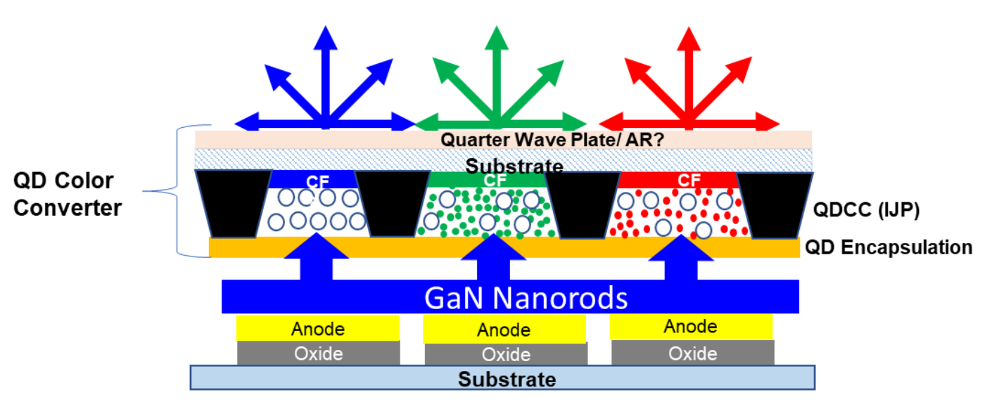
- QNED: Self emissive Blue GaN NanoLEDs (Nanorods) + QDCC;
- QD-uLED: Self emissive MicroLEDs + QDCC
Within the above 4 implementations, QD OLED and QNED are being pioneered by Samsung (Are Quantum Nano Emitting Diodes (QNEDs) the Next Big Thing?). QNED is still in R&D while mass production of QD OLED displays is planned to begin next year. Samsung had announced a $11 billion investment last year to be spent from 2019 to 2025 in “next generation displays” and has planned conversion of its G8.5 LCD line at Tangjeong: T8-1 to QD OLED. Further the company announced plans to end LCD production by end of this year and shifts its focus to QD OLEDs. Samsung’s QD OLED capacity as currently planned reaches ~ 6M m² input capacity by 2025.
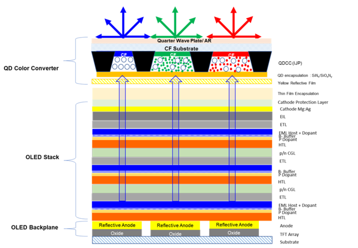
In the QD OLED architecture, a QDCC is used with a top emitting blue OLED backlight (also called “BOLED”). The color conversion is done by the red and green QDs in the red and green sub-pixels respectively, while the blue pixel is coated with scattering particles to enhance viewing angle. A secondary color filter is expected to be used. Pixel level control of light is achievable with the self-emissive blue OLED.
Samsung’ QD OLED Structure
Source: DSCC Annual Quantum Dot Display Technology and Market Outlook Report
There are knowns and unknowns in Samsung’s QD OLED structure. For example, the blue OLED stack is currently thought to be a top emission microcavity tandem structure with 3 emitting fluorescent blue layer stacks. Using 3 emissive layers distributes the current density among the EMLs during operation and leads to longer efficiency and higher lifetime. The top emission structure also helps increase the aperture ratio and helps with brightness and lifetime.
We have looked at a sample process flow for the QD OLED frontplane and backplane. With Samsung currently selecting IJP as the preferred deposition method, we have calculated the material usage for QD for an IJP process based on the QD OLED structure using a bottoms up approach with a best estimate of aperture ratios, bank thickness, concentration and density and that data is subsequently used for QD material revenue calculation for the QD OLED application. We made a first estimate of the material cost of QDCC frontplanes by IJP and we looked at Samsung’s QD OLED supply chain.
QNED: Samsung’s QNED technology in which GaN based blue Light Emitting Nanorod LEDs replace OLED as the blue light source. The advantages of the QNED structure over QD OLEDs include higher efficiencies, improved brightness, longer lifetimes and elimination of burn-in issues that have been associated with OLEDs. A simplified cross section of the QD-OLED and QNED device is shown below where the OLED is replaced by the GaN Nanorod LED. (for more see Are Quantum Nano Emitting Diodes (QNEDs) the Next Big Thing?)
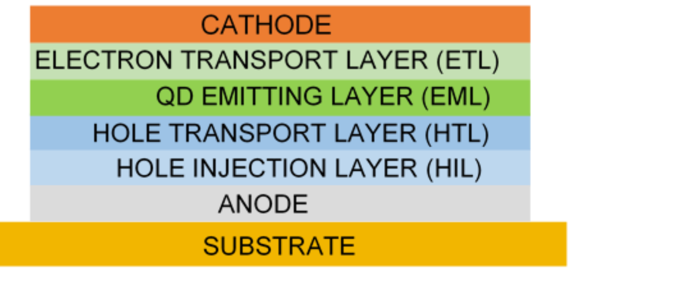
EL-QD: The ultimate goal in QD display technology is electroluminescence (EL) QDs, where the QDs are pumped electrically. EL-QDs follow an operating principle and structure like those of OLEDs although an argument could be made that EL-QD structures could be made simpler given the “purer” colors. The basic structure of both devices consists of an anode, hole injection layer (HIL), hole transport layer (HTL), QD emitting layer (EML), electron transport layer (ETL) and cathode. In this structure, electrons and holes are injected into the EML through the cathode and anode, respectively. The electrons and holes recombine in the EML to form excitons which radiatively decays to emit light.
EL-QD Device Structure
Source: DSCC Annual Quantum Dot Display Technology and Market Outlook Report
The lifetimes of EL-QDs devices still need to improve for use in RGB display applications although both Cd and Cd-free QDs have been making rapid progress. We looked at published efficiencies and lifetimes for EL-QD devices including some of the latest performance values from Nanosys, Nanophotonica, Samsung Advanced Institute of Technology and NajingTech. We looked at the challenges with IJP at large scale and we developed a sample flow for manufacturing EL-QD TVs by IJP and a timeline for production. TCL is also working on Hybrid EL-QD.
QD Market: Samsung Electronics has been the pioneer in QDEF TVs (sold as Samsung QLEDs) and the company has positioned “QLED” at price parity with OLED, limiting volume until 2018. In 2019, Samsung started pushing QDEF down in product line to the 6 series (was 8 & 9) as Vizio, TCL and Hisense launched their QDEF TVs (QLED) and QDEF is continuing to march toward becoming a mid-tier product.
Quantum dot-based panel shipments are forecast to grow from 3M shipments in 2018 to 31M shipments by 2025 representing a compound annual growth rate of 40%. The majority of shipments will use QDEF technology in TVs that reach ~ 20M panels by 2025, largely driven by lower prices and increased shipments by both Samsung and Chinese panel makers. QDEF is expected to continue to grow in other segments – monitor, notebook and tablets. QD OLED TV shipments are set to begin from 2021 with quantities reaching 3M panels by 2025. We made a forecast an emerging Hybrid QDEF Phosphor technology that we expect to penetrate different products and continue to grow. The adoption and growth of this technology will depend on its success and the price differential. QDOG Monitors continue to cater to very niche segments and the growth is limited. (Will QDOG Have its Day?)
QD Panel Shipment & Forecast by Units (2018-2025)
Source: DSCC Annual Quantum Dot Display Technology and Market Outlook Report
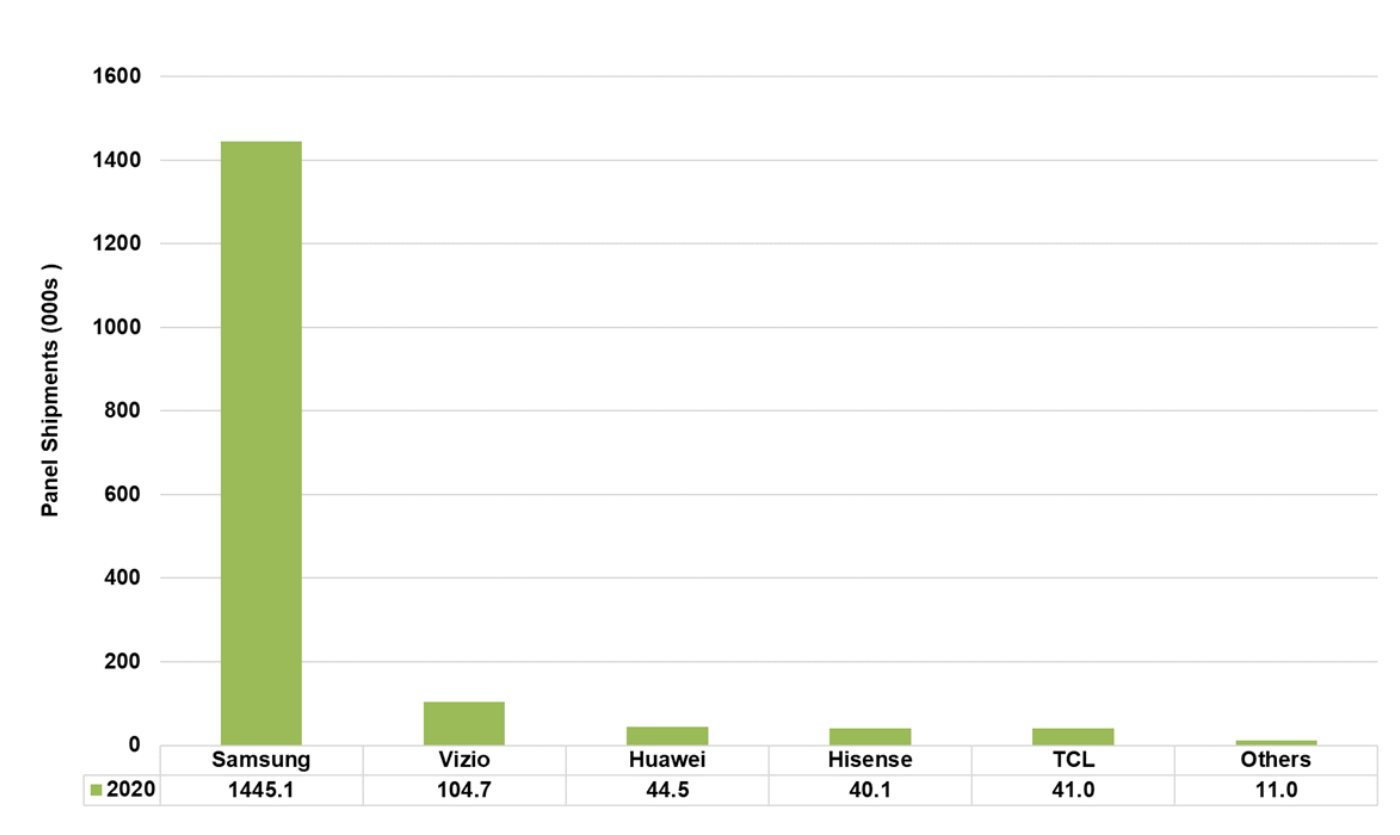
In Q1 2020, Samsung had more than 85% market share in shipments with a total shipment over 1.4M units. Vizio took the second spot while Huawei, Hisense and TCL have similar volumes.
QLED TV Panel Shipments by Units (Q1-2020)
Source: DSCC Annual Quantum Dot Display Technology and Market Outlook Report
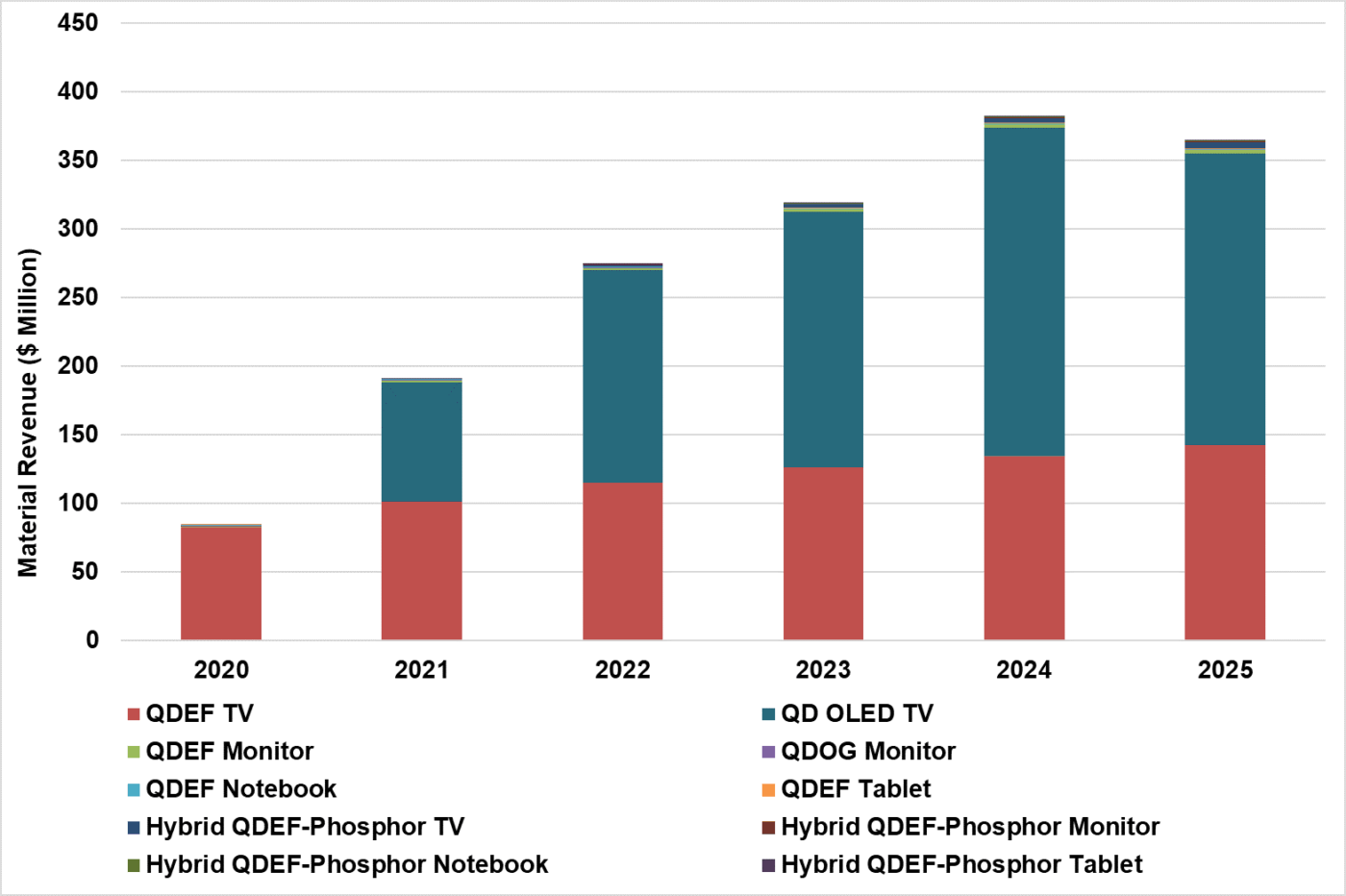
The overall QD Material Revenue is forecasted to reach ~$374M in 2024. The rapid growth is driven by both increased QDEF shipments but more so by the sizeable opportunity with Samsung’s QD OLED. The revenue begins to decline beyond 2024 to reach $354M in 2025 due to capacity limitations in QD OLED production. TVs continue to represent the largest segment for QD material revenue as the material scales proportionally to the display area.
QD Material Revenue Forecast (2020-2025)
Much of the data in this article came from the new DSCC report and you can find details here.

