Pete Palomaki has made the second in a series of YouTube videos in which he is tearing down a Samsung S95B QD-OLED TV. (Palomaki Rips Up a QD-OLED TV)This time he did a test that I had been wanting to see for a while and also clarified some questions about the structure.

There have been many rumours about the Samsung technology and the other day I was trying to remember – did the QD-OLED have a filter? I remembered hearing that it had and then I remember someone saying that it hadn’t. Hmmm – how to be sure?
The Question of Ambient Light
A second question that I had been thinking about since Display Week. As I mentioned in part one, at the beginning of Display Week, someone in a talk mentioned one of the tricky challenges of designing displays with quantum dots that perform colour conversion. If the quantum dots react to light (typically blue) to create red and green light, they can’t differentiate between the blue light coming from the display light source (a couple of blue OLED layers, mainly, in the case of the QD-OLED) and ambient light coming into the front of the display. If the QDs glow because of stimulation by the ambient light, the black level will rise and QD-OLED would lose dynamic range performance. That could be an issue. (as it was in the past for CRT and PDP phosphors)
At Display Week, I tried using the LED from my smartphone to make the QDs glow, but I had to get pretty close to the display to see the black levels rise, to the eye, and that meant that I was also seeing reflections from the LED light in the glass. Hmmm… that made it hard to work out what was the reflection component and what was caused by the excitation of the QDs.
A bright spark (and there are many of those at Display Week) pointed out that it would be better to use a UV torch as that would mean that there were no visible reflections and all we would see was the glow from the QDs – if there was something. We tried to meet up to test it the next day, when he could bring the torch. Trade shows being what they are, we missed each other, and it was the last morning, so I didn’t have the answer.
On To The Teardown
Pete has taken this on board and in his second teardown, one of the tests that he did was to use a UV torch on the QDs. His UV lamp did cause the red and green to fluoresce as you would expect. When the QD-OLED is in the TV, it is fitted with an anti-reflective film that is very effective at stopping reflections, but when Palomaki tried exposing the QDs to UV light through the AR film, blue light caused no QD emission – the film seemed to block everything – while strong UV excitation caused some QD emission, but it was very weak.
When the UV lamp was behind the QDs, they glowed, when it was the other side of the film, they barely did. On that basis, it seems clear that Samsung’s choice of film and the quantum dot design are doing a good job in blocking the unwanted emissions from the QDs in domestic conditions. That’s the Display Week question answered. As he said:
“It’s unlikely that we’re going to get just regular room lighting exciting this material”.
The Green OLED Layer Question
A second question was whether the blue layers of the OLED were the only ones in the emissive light source. There have been rumours of an additional green layer. Palomaki had earlier measured the green from the front of the screen (with the full display stack), but now the layers had been separated, he could compare that with the emissions of the QDs only (using the UV source). That showed that the red emission was pretty well the same in both cases, but the front of screen green had a slightly broader spectral power distribution. Palomaki thinks that the broader spectrum is an indicator that there is a green OLED layer as well as the blue.
There is a layer of some kind of film over the QD layer, when the panel was pulled apart, although he doesn’t think it looks as though it has an optical function. The layer seems to be conductive, so his suspicion is that this is an electrode layer that forms part of the OLED stack.
In looking closely at the pixel structure, Palomaki found that the green sub-pixel is very slightly larger than the red and blue.
![]()
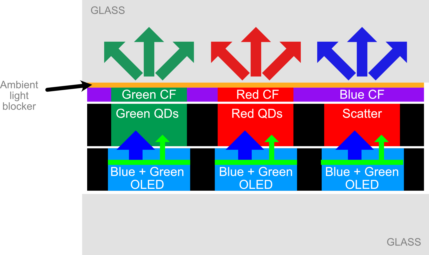
The Colour Filter Question
There is a colour filter on the top of the QD layers. He was surprised to find that there is a blue filter material under most of the area, not just where the blue pixels are. Again, the comparison of UV and white light exposure shows where the optical effects are coming from the colour filter and where they are the effect of the QDs. He included a simplified diagram of the structure that he found and so I re-drew it from his video.
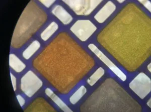
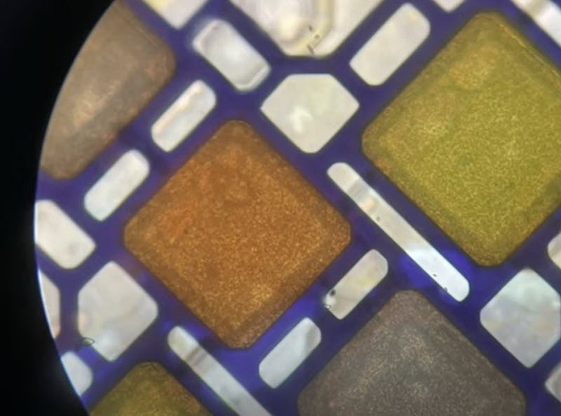
The QD Layer
Palomaki also had an interesting close up of the QD layer which shows that the QDs seem to be deposited in ‘wells’ in a ‘honeycomb’ structure. The QD materials are deposited in the holes in the structure and it is there to stop the pixels spreading and to get an even a result as possible. The QDs are just where the red and green sub-pixels will be. The blue sub-pixels have a clear material that just gives a more lambertian distribution of the light to match the blue light dispersion to be closer to the red and green QD emissions.
So there’s not much mystery any more about how the QD-OLEDs are put together and it’s clear that, as you would expect, Samsung has done a very good job of making sure that the QD-OLED panels perform really well in, it seems, almost any lighting environment. It will be fascinating to see what the firm can do with the technology, which is already winning awards everywhere for the TVs based on it, when the next generation of blue OLED materials finally gets to market! (BR)