
According to IDC, there will be 220,000 AR HMD units shipped in 2018, growing to 21.6 million in 2022, with most of these units going to the commercial market, not the consumer market. Ever wonder where these units come from? Where the designs come from? The design of a good HMD is not a trivial problem.
![]()
Advanced Helmet Mounted Display (AHMD) for helicopter training from 2005 designed by Link using Code V Software. (Credit: L3 Link)
The optics are probably the most difficult design problem in an AR HMD. Microdisplays, even OLED microdisplays, are a fairly mature technology, as are the wired and wireless protocols to connect them, the silicon ASICS to control them and the software to drive them. The near-to-eye (NTE) optics are a much less mature technology and, at this point, no one knows what is the best possible optical design is for a see-through AR HMD. This can be seen if you review the designs presented at SID 2018. I counted 25 SID papers directly related to the optical design of HMDs. This does not count the additional papers on HMD electronics, microdisplays, measurement instruments or human factors for HMDs. Not only are there are a lot of companies and universities designing the optics of HMDs, but they often take quite different approaches.
I had a chance to attend a webinar presented by Dr. Matt Novak, Code V Senior Customer Applications Engineer at Synopsys titled “Compact, High-Performance Optical Design: Meeting a Key Challenge in AR, VR, and MR Systems.” Code V is an optical design software package for imaging systems. It has been around for a long time and is now a subsidiary of the software company Synopsys. For example, I used Code V in 1991 when I did some optical design work for the GE Talaria projector. Code V isn’t the only optical design software that can be used to design VR and AR HMDs.
Zemax is, perhaps, its chief competitor, not that Dr. Novak mentioned Zemax in his webinar. Zemax has also been around for a long time and I used Zemax at Philips Research in the late 90s when I was working on the optics of consumer rear projection TVs based on both DLP and LCoS imagers. Of course, both Code V and Zemax have added many, many, many new features since I last used either program. Dr. Novak also emphasized that the current version of Code V is much easier to use that older versions. He added that most optical design work is done, in fact, by people who are not optical designers by training: they are EEs, mechanical engineers, Bio-photonic engineers, etc.
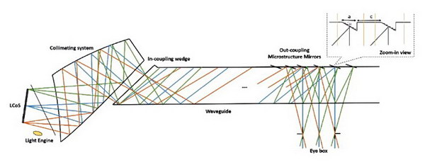 Example transmissive AR HMD using a collimating prism with freeform shapes on its three optical surfaces. (Credit: Synopsys)
One feature in modern software like Code V is the ability to efficiently handle freeform optical elements. Traditional optical designs used conic sections such as spherical, parabolic and elliptical surfaces. In particular, imaging applications such as AR HMDs would mostly use spherical surfaces. Aspherical surfaces are normally only used on-axis. There were two reasons for this. First, it was just too difficult to do a good imaging design using freeform surfaces. Second, if you had a good design using these surfaces, it was difficult or impossible to find someone willing to manufacture them for you with the required accuracy. Freeform surfaces are especially important when you want to design very compact, off-axis systems such as HMDs.
With modern design software and manufacturing techniques, the barriers to the use of freeform optics is at least reduced, but have not yet been completely eliminated. The Center for Freeform Optics is a joint university/industry research center that focuses on lowering the barriers even more.
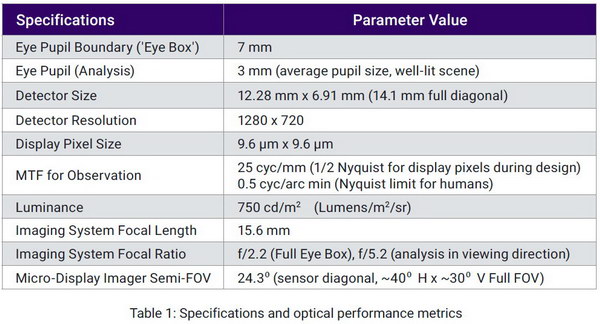 Target specifications for an all-reflective HMD design. (Credit: Synopsys)
The key part of the webinar was when Dr. Novak took the attendees through a step-by-step design process for the optics of a HMD. Because transmissive optics, especially ones made out of plastic, can have color aberration problems, he used as a Code V design example an all-reflective system. An added benefit of a reflective design is mirrors typically weight less than prisms, an important factor in HMDs. The big disadvantage of all-reflective designs is they are typically bulky and clumsy compared to transmissive designs. As a first step in the design process, it is necessary to establish target performance specifications for the finished system. The specifications for the demonstration design project are shown in the table.
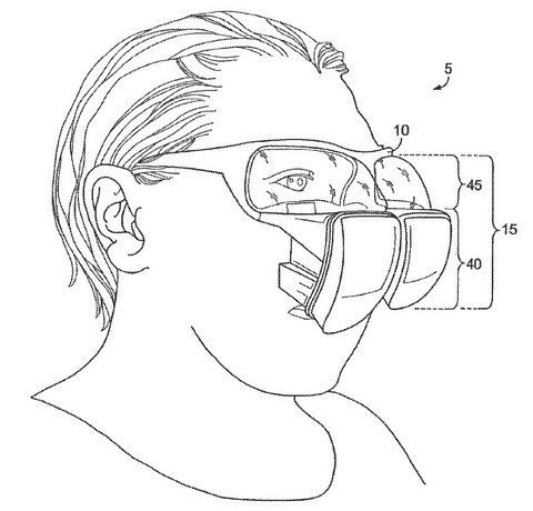 Figure 1 from US 9,151,954, assigned to Immy
The next design step is to search the patent literature for something similar. Dr. Novak found US 9,151,954, assigned to Immy, Inc. Regular readers of Display Daily would have seen this design before. It is a three mirror design and one drawing from the patent is shown above. As implemented by Immy in the NEO iC60 HMD Mk.1, the design is a lot less clumsy than the design shown in the patent.
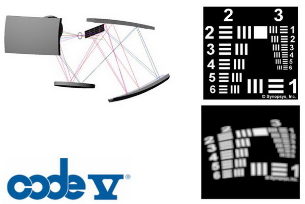 Starting Design for a 5-mirror HMD optical system (Credit: Synopsys)
The next step is to choose a starting design. Dr. Novak chose a five mirror design for his example HMD. While it has more mirrors than the iC60, each mirror is considerably smaller and the design can be folded to be beside the face by the ears, not above the eyes against the forehead or below them against the cheeks. Of course, as a see-through HMD, the final mirror must be in front of the eyes. This rough starting design using spherical surfaces has very poor optical performance, as can be seen by the test pattern and the simulated image of the test pattern. This design by itself is not acceptable and must be optimized.
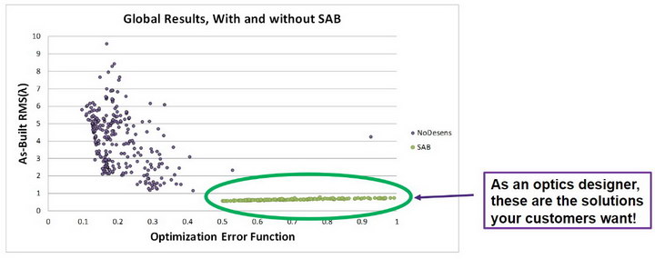 System performances in optimized designs compared to as-built designs. (Credit: Synopsys)
Dr. Novak emphasized the packaging and manufacturing of any optical design, especially one intended to be very compact like a HMD, must be considered right from the beginning of the design process. He said you can’t do an optical design and then package it after the fact. Typically this leads to serious tolerance problems when the design goes to manufacturing. He discussed two tools in Code V that help in this design-for-manufacturing task.
First, one tool explores a large variety of similar optimizations. A second tool then applies typical manufacturing tolerances to each system to estimate the as-built performance of a statistical universe of systems. In this design, the optimized design, if built exactly as specified by the design, can produce error functions as low as 0.1 – 0.4, as shown in purple in the figure. Unfortunately, when these systems are (virtually) manufactured with realistic tolerances, the errors balloon for the as-built systems from the 0.1 – 0.4 range to the 1.0 – 8.0 range. A second class of solutions, highlighted in green, have a higher error function in the optimized version, in the range of 0.5 – 1.0. In the as-built versions, however, the error function does not increase and remains in the 0.5 – 1.0 range.
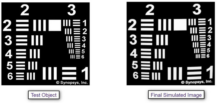 Simulated image of the optimized example design. (Credit: Synopsys)
Error functions don’t actually mean much to anyone except the optical designer himself. Code V will simulate the image produced by a design, more meaningful to an optical layman. As can be seen, in the final version of the example design with freeform surfaces, most of the distortion has been removed and the test patterns highlight the much higher MTF of the system, compared to the starting design with conic section surfaces.
 The final example optical design. Left is the font view and right is seen from the side, from behind the ear. (Credit: Synopsys)
The final example design is shown in the image This is much more compact than the Immy design. It makes extensive use of off-axis freeform surfaces. As an all-reflective design, it will not show any chromatic aberration. In addition, since mirrors are typically thin, the design may be lighter weight than a design using solid transmissive prisms.
This design is just an example of the use of some key features in Code V and, to the best of my knowledge, there are no plans to manufacture it. Does it violate the Immy patent, which also includes a five mirror version along with the three-mirror design? I read the patent and won’t even try to guess. A large part of the Immy patent deals with the mechanical structure of the HMD, not just the optical design, so it isn’t possible to tell if this design violates the patent until the opto-mechanical design needed to fix each of the five mirrors in its correct position has been done.
The complete webinar is on-line and can be streamed. On the webinar web page, there is a link to a white paper that goes into considerable detail on how to specify free-form surfaces using Forbes orthogonal polynomial deformations and Code V. According to Dr. Novak, Forbes polynomials are easier to turn into manufacturing specifications than the more conventional Zernike polynomials. Not that this is something most people need to know how to do. On the other hand, it is good for people (i.e. managers and marketing people) to know what it takes to go from a table of specifications, such as Table 1 above, to the final optical design. –Matthew Brennesholtz