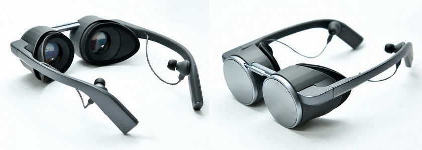
In yesterday’s Display Daily, I discussed the 2.6K x 2.6K Duo-Stack OLED device from Kopin with the ColorMax silicon backplane intended for VR/AR/MR applications. One planned application of this display is in a VR HMD from Panasonic. A VR HMD needs to be light weight and easily wearable for long periods and the HMD also needs a large field of view (FoV).

 The Panasonic VR HMD shown at CES 2020 used a Kopin OLED microdisplay and optics co-developed by Kopin, 3M and Panasonic. (Credit: Panasonic)
Kopin casually mentioned in the press release on this Duo-Stack OLED that the HMD system used ‘Pancake optics’. Recently, Kopin was granted a patent, US 10,459,215 B2 issued October 29, 2019, that described a thin, lightweight eyepiece suited for an OLED-based VR HMD. When I asked Dr. Hong Choi, Kopin’s Chief Technology Officer, if this patent described the Pancake optics used in the Panasonic HMD, he replied “The patent you referred to is not related to the Pancake optics. Panasonic is using the optics co-developed by 3M and Kopin, and Pancake is Kopin’s trademark for the optics.” Unfortunately, no information is available from Kopin as to exactly what the Kopin Pancake optics are.
Even if US 10,459,215 doesn’t describe the optics used in the Panasonic HMD, the patent is interesting because it allows a compact, lightweight package to provide a wide field of view from an OLED microdisplay. The optical design includes a refractive negative lens, two positive Fresnel lenses and, in most versions, a Diffractive Optical Element (DOE) to color-correct the chromatic aberrations introduced by the refractive Fresnel lenses.
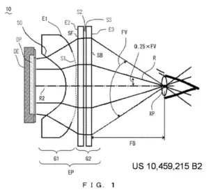
Layout of the optics in US 10,459,215 with two Fresnel lenses but no DOE.
The patent calls for the FoV of the optics to be at least 80° full field (FV in the diagram). According to the 1979 article cited by the patent by Toyohiko Hatada, et. al., “Induced Effect of Direction Sensation and Display Size Basic Study of Realistic Feeling with Wide Screen Display,” the feeling of “immersiveness” does not significantly increase when the FoV increases beyond 80° full field. Maybe, although there has been a lot of research on immersive systems since 1979. Still, this same article was cited by Sharp in a 2006 patent application., also related to immersive display systems.
The patent is also limited to devices no larger than 40mm (1.57”) in size. This limitation is not particularly significant and still allows the optics to be used with the 1.3” (33mm) diagonal 2.6K x 2.6K OLED microdisplay described in yesterday’s DD. In fact, on a cost basis alone, it is hard to imagine anyone wanting to build an OLED microdisplay for a HMD system with a diagonal greater than 40mm.
The general layout of the optical system is shown in the above figure, Figure 1 from the patent. DP is the display plane, i.e. the OLED layer. The eyepiece (EP) is divided into two optical groups, G1 and G2. In all examples in the patent, G1 consisted of only a single refractive lens with aspherical surfaces on both the front and rear surfaces. G2 consisted of, at a minimum, two Fresnel lenses, facing each other with the Fresnel surfaces S2 and S3. FV is the field of view, with a minimum target of 80°. The eyepiece directs the light to the pupil of the eye, XP. Note that light from different positions on the OLED device pass through the pupil at different angles – the light is not “focused” on the pupil. The lens of the eye then focuses the light from the OLED on the retina of the eye, not shown, to form the image.
There is one additional requirement on this or any other eyepiece for a HMD. The clearance FB (for back focal distance) between the last optical element and the eye, commonly called eye relief, must be at least 15mm so the eyelashes do not touch the optics.
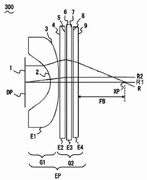
 Figure 21 from US 10,459,215 showing a Diffractive Optical Element (E4) added to G2.
The patent evaluates in detail five examples of this optical system, including all the data needed to evaluate each example on your own lens design software. These five examples are:
- Design shown in patent figure 1 with no Diffractive Optical Element. (DOE) (also shown in Fig. 7)
- The DOE (E4) is placed between the two Fresnel lenses, E2 and E3. (Fig. 14 in the patent)
- The DOE is placed after the second Fresnel lens. (Fig. 21 in the patent, shown above)
- The first Fresnel lens (E2) is made on a substrate that has aspherical curved surfaces on the front and rear. (Fig. 28 in the patent)
- The DOE is placed on the surface of E2 facing the display and the Fresnel lens is placed on the second surface of the element. (Fig. 35 in the patent)
One of the key advantages of the DOE is that it has chromatic aberration of the opposite sign than the chromatic aberration shown by normal optical glasses and plastics. Therefore, the DOE can correct the chromatic aberration produced by the refractive lenses. In the third example, as shown above, there was virtually no lateral or axial chromatic aberration in the system.
The patent points out that all of these designs produce images with pincushion distortion. This distortion can be corrected by adding barrel distortion to the video signal. Since this barrel correction is needed for virtually any HMD eyepiece design, the patent says this does not put any additional burden on the system generating the image.
Two things are not discussed in the patent that could affect usability and image quality produced by a design like one of these. First, there is no discussion of the eye box requirement in the patent. Eyeballs move around in the head and the HMD is not necessarily aligned correctly with the eye of the wearer. A finite eye box is needed to allow for these problems. In figure 21 from the patent, shown above, light ray R1 from the center of the display is parallel to the ray R2, also emitted from the center of the display but at a slightly different angle. This region of parallel rays from all points in the display is what defines the eye box. For example, ray R should have parallel rays coming from the same point on the panel as R but at different angles.
The other issue ignored by the discussion in the patent is resolution and MTF. If the display has, for example, 2.6K x 2.6K resolution, you don’t want this resolution to be lost in an eyepiece with poor imaging qualities. Since the Fresnel lenes are segmented, it is possible for them to significantly degrade the image quality, if they are not fine enough. If they are too fine, however, they can lead to diffraction and other problems.
These problems may be the reason this design is not used in the optics co-developed by Kopin and 3M and used by Panasonic in its HMD. Still, the idea of balancing chromatic aberration of conventional and DOE optics to minimize chromatic problems and it may have applications in future HMD optical designs. – Matthew Brennesholtz

