This session was somewhat misnamed – there was no discussion of volumetric displays, only one talk on light field displays and the only discussion of holography related to holographic optical elements (HOEs). As everyone knows (or should know), displays like Microsoft’s HoloLens have nothing to do with holography.
The first speaker in the session was Dinesh Padiyar, Research Scientist and Holographer at Triple Take Holographics, which is primarily an R&D company, not a manufacturer. He discussed the ability of HOEs to replace multiple conventional optical elements, reducing cost, size, number of elements and weight of optical systems, including HMD optical systems. HOEs can also do things that simply cannot be done at all using conventional optics. For example he discussed flat and curved HOE waveguides for use as the image combiner in see-through AR systems. Not surprisingly, he emphasized his company’s ability to design and master HOEs with predictable performance.
The second speaker was Seth Coe-Sullivan, VP of Technology at Luminit. Luminit designs, masters and manufacturers light shaping diffusers. Two examples he gave was a diffuser that worked uniformly over an 80° cone angle and a second that diffused over a 60° angle in one dimension and 1° in the other dimension. These are not HOEs but the master for them is made with a holographic-like process. The diffusers themselves are manufactured in large sheets using R2R processing. These diffusers are used for many applications from aircraft cabin lighting to fingerprint sensors, plus multiple applications in the automotive industry. He did not give an example of a HMD that used his company’s product, although he said they could be used in the optical combiner for a see-through AR HMD.
Next was Bernard Kress who was Principal Optical Architect of Google Glass at Google [X] Labs and is currently a Partner Optical Architect at Microsoft working on the HoloLens HMD. First he showed some graphs that showed AR was in the Gartner Cycle “Trough of Disillusionment” while VR was just beginning to climb up the “Slope of Enlightenment.” Hmm. Next, he showed some more AR/VR stuff, including another image from Minority Report. Finally he showed some more interesting images, exploded views of the Microsoft HoloLens see-through AR HMD. As can be seen, the HoloLens is completely self-contained, including a Windows 10-based computer. The CPU is not a general purpose CPU from a laptop but a dedicated CPU called the Microsoft Holographic Processing Unit (HPU 1.0). Of course, there is nothing holographic about the processor and the only thing “holographic” in the system is the HOE optical combiner.
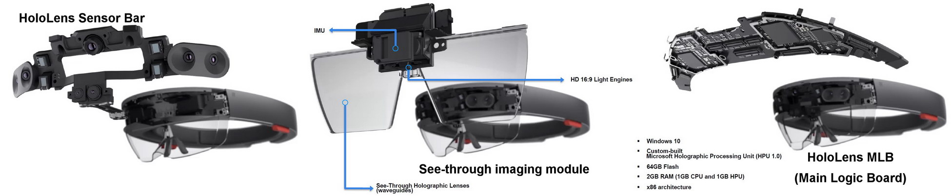 Exploded Views of the Microsoft HoloLens. Left: The sensor bar includes multiple cameras and light sensors. Center: The Imaging module. Right: The main logic board. (Source: Microsoft)
Finally, he discussed several issues likely to be needed for next-generation HMDs from Microsoft and others such as Google. The ones he discussed were:
- Optical Foveation
- Increased brightness needed for see-through AR
- Hard edge occlusion, similar to what Richard Marks from Sony discussed
- Vergence/Accommodation Conflict (VAC) mitigation. This was a topic that was discussed by several authors in the Technical Sessions, so I won’t discuss it further here.
Optical foveation (or foveated rendering – a more widely used term – Man. Ed.) is a technique designed to reduce the 100Gbps or so VR bandwidth requirements discussed by Daryl Sartain of AMD and Clay Bavor of Google. It involves showing the full resolution image only on the foveal region of the eye, where the resolution can be appreciated. The rest of the HMD imager would show a reduced resolution image requiring reduced bandwidth, as shown schematically in the figure.
Strictly speaking, this figure is labeled wrong and the vertical axis should be labeled “Display Bandwidth” not “Display Pixel Count.” This is because, with foveation of the image, the entire display needs to be high resolution. A high resolution image is only delivered to the portion of the imager where the eye is pointing and low resolution is delivered everywhere else. This reduces the amount of data the display needs, but, since the eye can point anywhere on the display, it does not reduce the required pixel count. This is not a new idea – I first encountered it in Talaria projector-based flight simulators in the 1980s.
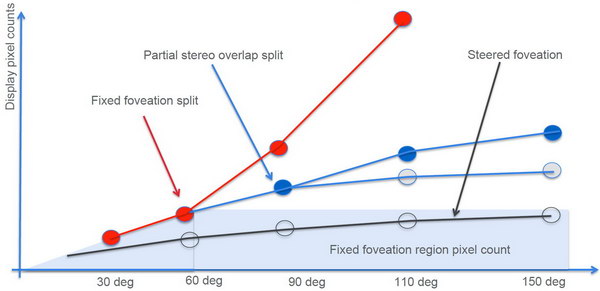 Foveation of the VR/AR image to reduce bandwidth requirements. (Image: Microsoft)
Foveation of the image would require significant software to implement, a problem that probably doesn’t worry Microsoft. It also might increase latency, although with the processor and cameras built into the HoloLens HMD, this maybe less of an issue. Since the processor is custom for HMD applications, it can be designed with special functions to accelerate the foveation computations. Of course, foveation requires reliable eye tracking but since there are so many sensors built into the sensor bar of the HoloLens already, this shouldn’t matter too much.
The final speaker of the session and of the AR/VR Business Conference was Thomas Burnett, CTO, founder and primary investigator of Fovi 3D. Fovi 3D is developing true light-field displays (LFDs). He explained how a LFD differs from a conventional 2D display, a stereoscopic 3D display or a multi-view 3D display. Since I’ve encountered LFDs before, I knew what he was talking about but I wonder if people who were encountering LFDs for the first time could sort out the difference between a pixel, a hogel and a voxel.
Like a multi-view 3D display, a light field display gives a glasses-free 3D image. However, unlike a multiview display, there are no viewing zones and no conflicts between accommodation and vergence with a LFD. In practice, a LFD comes the closest to a true holographic display that is available with 2017 technology. Burnett cited several studies from the 2007 – 2013 time frame showing better task performance when a LFD was used instead of a conventional 2D display.
There are two key reasons why light field displays are not common, at least not yet. First, they require a large amount of computing power to turn 2D, stereoscopic 3D, 3D+depth or multi-view 3D images into light field images. I know of no native light field image formats and if they exist, Burnett didn’t mention them. While this computing power was a significant problem with early light field displays, with modern GPUs packing large amounts of power into relatively inexpensive chips, it is not a critical problem now. The more significant problem is the very large number of pixels need to display light field images.
The basic structure of a Fovi 3D LFD array is shown in the image below. It consists of an array or Spatial Light Modulators (SLMs or microdisplays), an array of tapered fiber optic arrays to fill in the gaps between the SLMs and a microlens array to direct the rays from each SLP in the correct directions. From this simple structure, it appears as if Fovi 3D is using emissive (i.e. OLED) microdisplays, although LFDs in the past have often used arrays of picoprojectors. Note that the full area of the display is filled with SLMs. He discussed a VGA display with 1mm pixel resolution. Can you imagine the cost of enough eMagin or Kopin OLED microdisplays to fill a 640mm x 480 mm area?
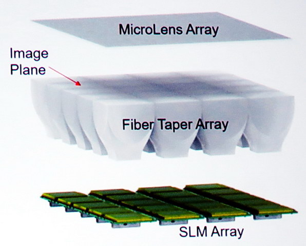 Structure of a Fovi 3D light field display (Image: Fovi 3D)
In an LFD, you need to consider both spatial and angular resolution. Burnett discussed two displays, each with 100 ray angles and one with a 30° FOV and the other with a 90° FOV. These corresponds to 18 arc-minutes and 54 arc-minutes resolution respectively, both much lower resolution than the 1 arc-minute resolution of the human eye. Perhaps this is not the right way to evaluate angular resolution of a LFD, but no one I know of has ever offered a better method.
Burnett discussed his company’s Gen 2 LFD proof-of concept module. This is an array of 80 x 16 monochrome yellow hogels with a 90mm x 20mm active area, giving approximately 1.2mm spatial resolution. The unit has a FOV of 90° with 118 x 118 angular resolution per 90°, giving an angular resolution of 45 arc-minutes. This may prove Fovi 3D can built a LFD but, for the time being, the high cost and modest spatial and angular resolution of LFDs is likely to limit them to niche markets such as military maps. Fovi 3D will be delivering their LFD developer kit, the Fovi DK2 in Q3 2017.
Analyst Comments
The AR/VR Business Conference was well attended and provided a good overview of the fields of Augmented Reality and Virtual Reality for those attendees new to the field. Attendees were given electronic copies of the presentations and these may be available to others – contact the DSCC to ask about their availability.
The conference also provided a good cross-section of forecasts for AR/VR, enough to justify its title as a Business-Track Conference. The fact that these forecasts vary wildly from each other does, in fact, represent the state-of-the-art of forecasting AR/VR hardware and software unit sales and revenue. Businessmen and investors be warned! – Matthew Brennesholtz
 The attentive audience at the SID’s AR/VR Business Conference. (Photo credit: M. Brennesholtz)