See-Through AR Displays
Many see-through AR displays are based on waveguide optics. The entire session 17 was dedicated the technology of improved waveguide optics, with a focus on the optics that couple the image into and out of the waveguide. While paper 17-1 and 17-2 used waveguides in their optics, they were not used in the conventional ways and they were described elsewhere in this SID Special Report.
 Two-waveguide based see-through AR display from Sony. (Source: SID 2018 paper 17-3)
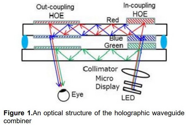
On the other hand, paper 17-3 from Takuji Yoshida and his colleagues at Sony and titled “A Plastic Holographic Waveguide Combiner for Light-weight and Highly-transparent Augmented Reality Glasses” used a classic AR waveguide design, with improved and lower cost elements. These relatively straight-forward technology improvements put the design much closer to production than the research versions of see-through AR displays. This is similar to the two-layer waveguide system from DigiLens (paper 17-4) described elsewhere in this special report with two major differences. In the Sony approach, the red and blue portions of the image share one waveguide and the green uses the other. In the DigiLens design, the blue and green share one waveguide and the red uses the other waveguide. Another, perhaps more important, difference is the HOEs in the Sony system are laminated to the outside of the waveguide. In the DigiLens system, the Bragg grating HOEs are formed inside the waveguide, which is likely to protect them from damage.
Sony provided a surprising amount of information relating to the manufacturing of this waveguide system. This included materials used for both the HOE and the injection molded plastic waveguide and assembly tolerances. They showed data that the plastic waveguide provided the same image quality on-axis as a glass waveguide and only slightly poorer quality ±8° off-axis. I suspect this system is near production, if it isn’t in production already.
Paper 17-4 described the DigiLens waveguide system. Since I visited the DigiLens meeting room and got a detailed explanation of their technology and market plans, this system is described in a separate article.
 Three waveguide system from the University of Central Florida (Source SID 2018 paper 17-5)
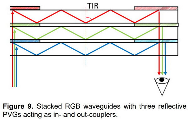
Paper 17-5 from Kun Yin and his colleagues at the University of Central Florida and titled “High Efficiency Polarization Volume Grating for Waveguide-based AR Displays” focused more on the manufacturing process for HOE elements at the entrance and exit regions of the waveguides than the waveguides themselves. The polarization volume grating (PVG) is produced with a holographic process and is designed to reflect right-handed circularly polarized light and transmit left-handed circularly polarized light that is in the PVGs operational bandwidth. Other wavelengths of either polarization are transmitted through the PVG. The authors gave an example of a design of a three-waveguide system that could be made with their PVG HOEs.
 (Source: SID 2018 paper P-95)
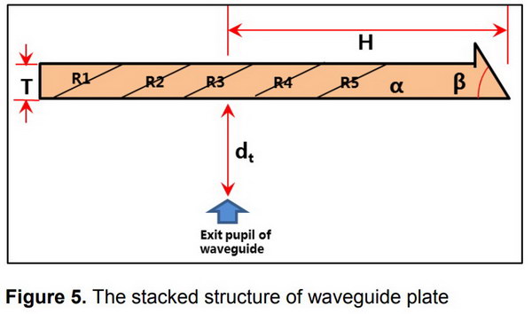
Poster paper P-95 titled “Study of AR Optical Design with Lightweight Optical Waveguide” was from Naifu Wu and his colleagues at the BOE Technology Group. The see-through waveguide resulting from this study had a thickness of 2.5mm, an eye relief of 20mm and a FOV of 35°. It was also optimized to reduce the stray light in the system which can otherwise result in ghost images in the AR image.
Poster paper P-97 titled “Optical Configuration of VR Systems for Slim and Light Head Mounted Displays” was from Sung-Min Jung and his colleagues at the LG Display R&D Center. While the design was, in fact, slim and lightweight, it also had 20% of the optical efficiency of a conventional see-through AR HMD design. Since AR HMDs are already too dim, any design that reduces the brightness by an additional 5x is a non-starter.
Poster paper P-98 titled “Incorporating Space-variant Holographic Grating in Waveguide Display” was from Chao Yu and his colleagues at Zhejiang Universityand The University of British Columbia. In most see-through AR HMDs, the holographic grating that couples the light out of the waveguide and into the viewers eye is spatially uniform. By using a HOE with spatial variation, they improved both efficiency and FOV for both white and coherent light.
Eye Tracking for AR/VR applications
High speed eye-tracking from BOE (Source: SID 2018 paper 30-2)
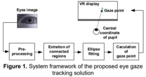
Eye tracking is an essential part of many advanced AR and VR system designs, including all designs that use any form of foveated rendering. To be useful, eye tracking must be done very quickly to minimize latency and allow the latency budget to be used for other things such as rendering the foveated images and transmitting them to displays. Paper 30-2 from Quan Yang and his colleagues at BOE is titled “Implementation of a Real-time Eye Gaze Tracking Solution for ASIC Based on VR Display.” This paper describes an eye-tracking ASIC, prototyped on a Xilinx kintex-7 platform, that showed a 380Hz eye-tracking sampling rate. This high speed was achieved by bypassing the main processor and its overhead that normally slows down the process.
SLAM Tracking
Simultaneous Localization and Mapping (SLAM) is a key part of virtually all mobile systems, including six degree of freedom (6DOF) VR, see-through AR, autonomous automobiles, robots, etc. Several advanced SLAM techniques were reported at SID in the AR, VR and AI technology track.
For those not familiar with SLAM, there was paper 37.3 by Harsh Menon and his colleagues at Nod Labs and titled “Deep-Learning based Approaches to Visual-Inertial Odometry for Autonomous Tracking Applications.” This invited paper provided a review of AI and neural net-based SLAM systems that use computer vision and inertial sensors as input. One of the focuses of the paper was on how to merge data from the two different types of SLAM sensors to provide a coherent map of the world surrounding the mobile system.
![]() Tracking system from 6DOF Space is capable of tracking at 1000Hz using ambient light sources. (Source: SID 2018 paper 30-3)
Tracking system from 6DOF Space is capable of tracking at 1000Hz using ambient light sources. (Source: SID 2018 paper 30-3)
SLAM tracking is a key requirement for 6 Degree of Freedom (6DOF) VR systems. It is essential in a 6DOF system to minimize latency in order to not only minimize VR sickness but also prevent disorientation of the mobile VR HMD user for safety and other reasons. Paper 30-3 from Klony Lieberman and his colleagues from Sixdof Space presented a paper titled “Ultra-High-Speed 6DOF SLAM using Optical Compression.” This paper describes a system that uses a one dimensional array and a toroidal lens to track ambient light in the VR HMD wearer’s space. This can be done with a latency of less than 1mS. In order to track all six degrees of freedom, it is necessary for the HMD to have three sensors similar to the one shown.
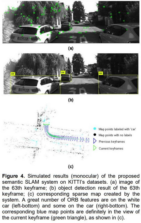 SLAM tracking in an automotive application. (Source: SID 2018 paper 30-4)
A different approach to SLAM was given in paper 30-4 titled “Semantic Simultaneous Localization and Mapping for Augmented Reality” from Bing Yu and his colleagues at Shanghai Jiao Tong University. Not only is this a different approach but it is looking at a different market since the system can generate neighborhood maps of relatively large neighborhoods. The example given by the authors was tracking a car’s position relative to other stationary and moving cars plus fixed obstacles as it moved down a street and around a corner. As such, the paper could have been in the automotive track rather than the AR/VR track. On the other hand, the system could also be used to track an AR or VR HMD wearer as he wandered around in an unknown building. For example, a firefighter in a smoke filled building wearing a smoke-penetrating IR HMD could be tracked while generating a map of the building for others to follow. The system was based on previous YOLO (You only look once) and ORB-SLAM2 systems. Latency is not quite as critical an issue in automotive or AR applications as it is in VR applications and the system achieved 29mS mean tracking time with monocular input and 54mS tracking time with stereo input. –Matthew Brennesholtz