There were two sessions at the SID technical symposium that focused on the technology for projection systems: Session 63: Projection: Image Improvement and Session 70: Projection: Screen Technology.
Projection Technology
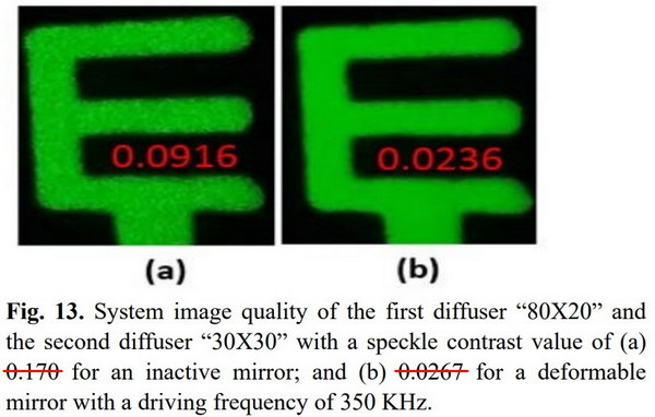 With diffusers alone, speckle was still visible in the best combination of diffusers (a). It became invisible with the Dyoptyka mirror turned on. Note the errors in the original caption. (Source: SID 2018 paper 63.1)
Paper 63.1 was titled “Speckle Reduction for Laser Pico-projector with Dynamic Deformable Mirrors” and was from Che-Wei Tsao and his colleagues at National Chiao Tung University and the Chi Mei Medical Center. Their speckle reduction system involved a Dyoptyka miniaturized phase-randomizing deformable mirror and two fixed diffusers in a DLP-based picoprojector with red, green and blue lasers. The Dyoptyka mirror was used as a fold mirror just before the light pipe integrator and the two diffusers were at the input and output surfaces of the light pipe. Diffusers are needed in a system like this to increase the étendue of the laser light source to the point where the light pipe can provide uniform illumination to the DLP imager. Moving diffusers are often used to supress the visibility of speckle but this study involved only stationary diffusers.
 (Source: SID 2018 paper 63.1)
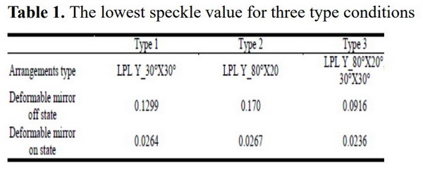
Speckle contrast was evaluated quantitatively by a camera with an f/# and integration time similar to the human eye. With the mirror turned off, all combinations of diffusers including the best combination, Type 3, produced visually unacceptable speckle in the system and relatively high values of speckle contrast. With the mirror turned on, speckle was visually acceptable and speckle contrast values were quite similar for all combinations of diffusers.
 (Source: SID 2018 paper 63.2)
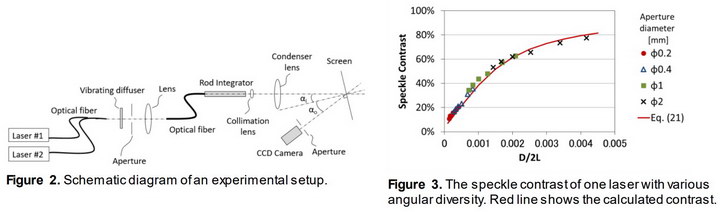
Paper 63.2 titled “Dependency of Speckle Reduction by Wavelength Diversity on Angular Diversity in Laser Projection System” is from Hirotaka Yamada and his colleagues at Ushio Inc. (Note; I believe there is a typo in the title and the authors intended “…Wavelength Diversity and Angular Diversity…” MSB) This Distinguished Paper, available in extended form for free download from the Journal of the SID website, is a rather complex mathematical analysis of speckle. In the end, the researchers compare their calculated values of speckle with measured speckle, with good agreement. This analysis removes one of the mysteries from projection speckle by showing it is something that can be forecast for an optical system.
(Source: SID 2018 paper 63.3)
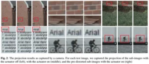
Paper 63.3 titled “Real-time Spatial-based Projector Resolution Enhancement” was from Avery Ma and his colleagues at the University of Waterloo and Christie Digital Systems. This system discusses an algorithm to extract the two sub-images to be shown on a projector that includes pixel shift. The algorithm differs from existing algorithms in that it pre-distorts the two sub-images to compensate for the optical aberration inherent in the projector-lens system. As can be seen in the image above, this leads to a very modest improvement in image quality at the pixel level.
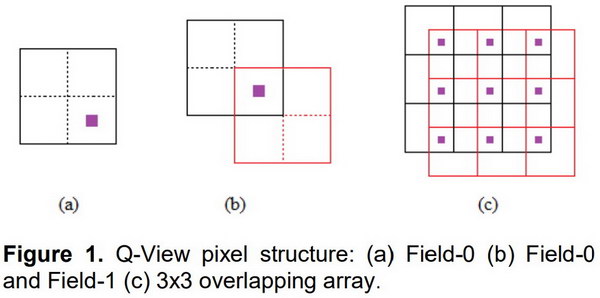 In Syndiant’s Q-View system, core (physical) pixels are grouped in two overlapping arrays of super-pixels. (Source: SID 2018 paper 63.4)
Paper 63.4 titled “Q-View Technology – Approach to Achieving High Resolution and Low Power in Small Pixel Micro-Display” is from Craig Waller and his colleagues at Syndiant, Inc. This paper describes a virtual implementation of pixel shift on a high-resolution LCoS imager. In the Q-View system, four core pixels are grouped together as a single super-pixel. A high resolution image is then broken down into two sub-fields and displayed on super-pixels made from two different groups of core pixels, as illustrated above. The example the authors gave was a UHD (3840×2160) array of pixels grouped as two FHD (1920 x 1080) arrays of super-pixels. Then a UHD image is shown on the array as two fields. The advantage of this approach over just showing the UHD image on the UHD array, the authors said, is the Q-View technology maintains the data bandwidth and power consumption of a 1080p FHD display. Well, maybe.
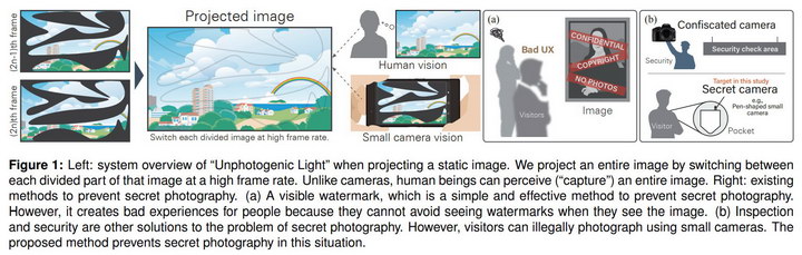 (Source: SID 2018 paper 70.1)
Paper 70.1 titled “Unphotogenic Light”: Evaluation and Detail of the High-Speed Projection Method to Prevent Secret Photography with Small Cameras was from Ippei Suzuki and his colleagues at the University of Tsukuba and Pixie Dust Technologies, Inc. This paper hardly needs more explanation than what the authors provide in the caption of their figure 1. The authors do not discuss the fact that their system will cut the effective output of a cinema projector in half. They also don’t discuss the likelihood that a camera with a programmable shutter speed will be able to defeat their system. They do mention that some viewers of their demonstration see flicker from the two-field approach to image projection. All-in-all, I would say this would be tough to sell to the cinema industry.
Projection Screen Technology
Paper 70.2 titled “Projection-based Multi-view Three-dimensional Display with Angular Steering Screen” was from Xinxing Xia and his colleagues at the Nanyang Technological University, Singapore. This was a time-multiplexed autostereoscopic system where the images from each of 12 portable DLP projectors with the resolution of 640×360 were multiplexed into left, center and right positions, creating a super-multiview autostereoscopic system with 36 views. The angular steering screen was based on two pi-cells, each the full size of the projection screen, and polarization-sensitive micro-prism arrays. Of course, polarization-sensitive beam steering is not a good match for unpolarized DLP projectors.
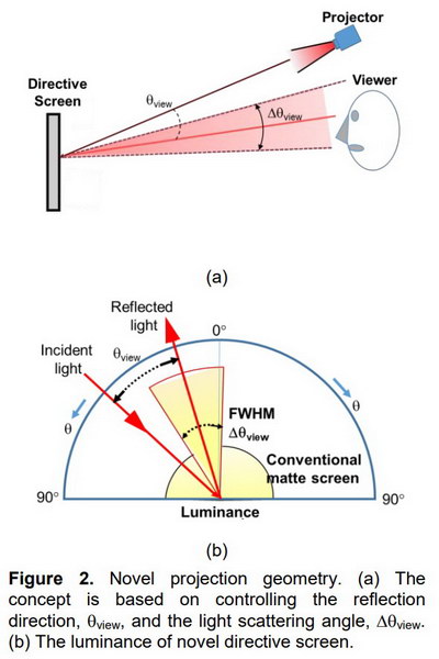 (Source: SID 2018 paper 70.3)
Paper 70.3 titled “Novel Directional Projection Screen using Diverted Curved Surfaces Cube Corner Reflector (D-CCR)” was from Ryosuke Ohtera and his colleagues at Sendai College, Tohoku University and Global Optical Solutions. This is a high-gain screen (gain=16) that is based on a large array of small, modified corner-cube reflectors. True corner-cube screens can and have been built but have two major problems. First, the image is retroreflected back toward the projector and the viewer is not normally co-located with the projector. Second a true corner-cube system has a very, very high gain and therefore a very, very small viewing angle. The authors control the viewing space problem by designing the corner-cubes not to retroreflect, but send the light back somewhat off-axis at an angle they call θview. The design can be arranged so when the projector is above the optical axis, the reflected light comes out perpendicular to the screen.
The second problem, FOV of the screen, is controlled by slightly curving each face (or one face) of each corner-cube, providing diffusion of the light through a finite angle (Δ θview) determined by the amount of curvature. The authors made several D-CCR screen samples each with a size of 100 x 100 mm although I would say the photos in the paper were unconvincing of the value of the design. On the other hand, since the screen addresses problems with real screens and everything the authors describe could probably be made using micro-embossing and roll-to-roll processing, the approach is worth pursuing.
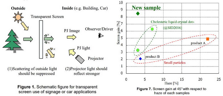 Left: The geometry of a transparent screen intended for front projecton. Right: the improvement of the new sample over previous designs. (Source: SID 2018 paper 70.4)
Paper 70.4 titled “Higher-Contrast and Lower-Haze Transparent Screen Using Waving Cholesteric Liquid Crystals” was from Yujiro Yanai and his colleagues at Fujifilm Corporation. Transparent screens are often used in shop windows for digital signage applications. An image is projected on the screen and a viewer inside or outside the shop can see both the projected image and the real objects behind the screen. For this to work right, the screen needs the highest possible gain at its design angle and the lowest possible haze. This new design from Fujifilm has higher gain (8.5%) and equal or lower haze than previous designs. Note that “highest gain” is still very low – 0.085 compared to 1.0 for a matte white screen or 16 for the screen described in paper 70.3 but neither of those screens would be transparent. -Matthew Brennesholtz