There were three papers in the Light Field Display session (61) at SID DisplayWeek. First was Thomas Burnett of FoVI3D, formerly Zebra Imaging. He started his talk with a very nice definition of a light field display, which is instructive to show below as the use of the term is not very consistent within the industry. His definition:
- Reproduces a 3D aerial image visible to the unaided eye without glasses or head tracking
- Perspective correct visualization within at least one viewing plane, either horizontal or vertical (preferably both) within the display’s projection volume
- Binocular disparity, occlusion, specular highlights and gradient shading and other expected depth cues must be correct from the viewer’s perspective as in the natural real-world light field
FoVI3D is working on an integral imaging type light field display system that will have horizontal and vertical parallax. Such systems are very computationally challenging and performance is partly limited by current GPUs and APIs which do not support multi-view rendering natively.
For example, to create a simple stereoscopic image requires two passes through the GPU rendering engine at slightly different viewing positions. Now imagine that this has to be done dozens or hundreds of times for a light field display. As a result, they have proposed and are developing a new rendering architecture, as shown below.

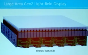
In their system, OLED microdisplays and microlens arrays comprise the top half of the display. What is innovative is the use of dedicated radiance image (hogel) computation that is done in parallel at the display and not in the PC.
Burnett then described two common methods for generating hogel (one microlens element) data. These are the double frustrum and oblique slice and dice methods – each having its advantages and disadvantages depending upon the application. His assessment was that the oblique slice and dice will take too much time to hope to achieve a real time solution, so they use the double frustum method.
To solve the serial nature of rendering in modern GPUs, FoVI3D is developing the Multiview Processing Unit (MvPU) that will allow multiple viewports to be rendered in parallel. In addition, they will need to develop an new API that “permits and optimal and easy to use definition for geometry and materials while providing constructs that a multi-view/lightfield render solution can implement to accelerate rendering.” FoVI3D is now working on implementing these new Gen 2 ideas via Navy and AFRL contracts.
Motohiro Makiguchi from NTT described an approach to a horizontal-only projector-based display system that can reduce the number of projectors needed to obtain similar image quality. While this was in the light field session, it does not appear to be a light field system as it does not meet the definition described above. Instead, it is more accurately an aerial image with depth perception only via horizontal motion parallax. In other words, users are not presented a stereoscopic image, but a series of 2D images. A viewer can perceive depth by moving their head to see alternative views. Transitions are seamless because a linear image blending technique is used to smooth the transition from one view to the next.
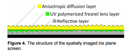
Previous work to smooth the image was limited in image size and viewing area. The new work described a new screen technology composed of Fresnel lens, back reflector and diffuser to create a larger aerial image with wider FOV (figure 4).
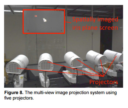
Experimentally, the group constructed two of these 50” screens and mounted them back-to-back. At the Niconico Chokaigi event this year in Japan, NTT set up the system with thirteen projectors illuminating each screen to create the aerial image (like Figure 8 but with more projectors). Each projector was connected to its own PC. In the presentation, Makiguchi showed a video of the camera moving from one side of the image to the other. Multiple views of the object, which appeared to be behind the screen, were shown as the camera started to move in the half circle until. At around 30 degrees off the center normal, the image disappeared but reappeared on the other side as the camera swing was completed.
This system has allowed NTT to reduce the distance between projectors with their smoothing algorithm while increasing the FOV. NTT is developing this solution for video conference applications so users could see their counterparts and be able to have depth perspective as they move their heads. Future work will focus on developing a life-sized version and recording and transfer of live action images for realtime communication.
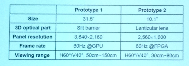
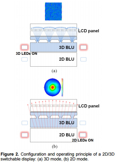
Jin-Ho Lee from Samsung Advanced Institute of Technology (SAIT) then described a 2D/3D switchable display that used eye tracking to adjust the delivered image. He did not offer any details to suggest this had light field properties, so it seems to be more of a multiview autostereoscopic display. They built two prototypes as detailed in the table below.
Key to these prototypes were two new backlight designs that allow the display to be in 2D or 3D mode. The backlight design for the parallax barrier version is shown below. These are long bar-type structures. The lenticular version moved to an island-type extraction structure which allowed for both vertical and horizontal parallax. Perhaps this is how they justified calling it a light field display.
With the 18.4″ prototype, the group achieved a brightness of 310 cd/m² in 2D mode and 80 cd/m² in 3D mode. For the 10.1″ prototype, they achieved a brightness of 300 cd/m² in 2D mode and 125 cd/m² in 3D mode. Both achieved a brightness uniformity of over 80% in both modes. Crosstalk ranged from 6% to around 9% at a 30º angle. These results are interesting but the added thickness, power and uneven brightness levels does not seem to make them very attractive. – CC