One of my Display Daily’s last fall was titled “Ultra-Thin Cameras for Thinner Smartphones.” Those ultra-thin cameras were mostly based on computational photography, where the raw data from the image sensor requires serious computation to extract the picture from what, to the human eye, often appears to be pure noise in the raw sensor data.
![]()
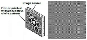
Encoder aperture plates used by Hitachi (left) and Rice University (right) in their ultra-thin cameras. (Credit: Left Hitachi, Right Rice University)
Two of the cameras I discussed in that DD came from Hitachi and Rice University. The architecture of both cameras was similar, with an encoding aperture plate separated by a small distance from a conventional 2D image sensor. The Hitachi camera (left in the image) used a series of concentric circles while the Rice University camera used a binary-encoded pattern. The raw data from the image sensor was then decoded from the sensor data into a 2D image.
A team of researchers led by Nick Antipa and Grace Kuo and working with Laura Waller, Assistant Professor of electrical engineering at the University of California Berkeley and head of the Computational Imaging Lab, have developed a similar system they call the DiffuserCam. They have shown that using a pre-determined pattern is not necessary or even always desirable. Instead of a fixed pattern, they used a standard, off-the-shelf, surface contour diffuser from Luminit with a diffusion angle of 0.5°. This they spaced 8.9mm from a standard, off-the-shelf color camera sensor from PCO. One of the advantages of using a diffuser instead of a pre-determined mask, according to the Berkeley researchers, is that a diffuser transmits all of the light to the sensor. The masks used by Hitachi or Rice University are partly opaque and block some of the incoming light, reducing the sensitivity of the camera.
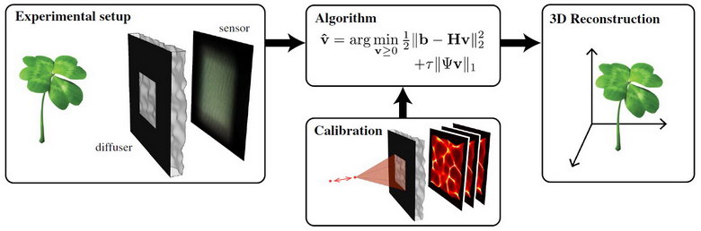 DiffuserCam system from researchers from the University of California Berkeley. (Credit: UC Berkeley)
In the image, the diffuser and sensor are shown on the left. Note there is an opaque mask on the diffuser. This is done to ensure all the diffused light falls on the image sensor and does not go beyond the active area of the sensor. Unlike the masks in the Hitachi and Rice systems, it does not encode the image. The mask also does not restrict the field of view (FOV) of the system, as one might expect. Instead, the FOV of the DiffuserCam is set in the mathematics of the decoding algorithm where the off-axis modulation transfer function (MTF) falls to the point where it is meaningless. The FOV in the prototype was also limited by the fact that the camera pixels had limited FOVs. The overall FOV for the Berkeley demonstration unit was ±42° in x and ±30.5° in y.
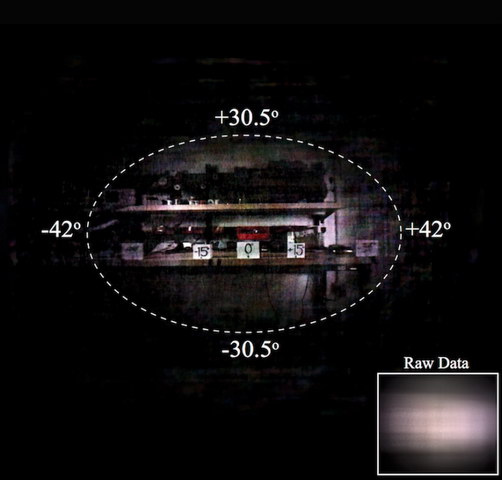 The DiffuserCam team at Berkeley confirmed their FOV calculation with an image. (Credit: UC Berkeley)
The DiffuserCam system requires calibration. The calibration, in practice, characterizes the diffuser used in a particular camera including its spatial and angular properties and its alignment relative to the pixel array. This calibration is done by capturing the image produced on the sensor by a point source placed at a variety of positions along the optical axis of the DiffuserCam. In the demonstration unit, calibration images were taken at 128 different z-planes, ranging from z = 10.86 mm to z = 36.26 mm from the diffuser. In a practical flat camera, for example, one designed to be built into a smartphone, this would need to be done for each camera produced. Alternatively, if the surface diffusers were produced by an accurate replication procedure and were then aligned accurately to the pixel array of the sensor, it would be possible to use the same calibration data for each camera.
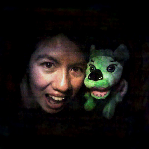 Still Image of Grace Kuo and a stuffed dog taken with the DiffuserCam demonstration unit. (Credit UC Berkeley)
For the demonstration DiffuserCam, with a 1.3MP sensor, it is said to be possible to deconvolve the raw data into 100M Voxels. There is a very strong caveat on this decoding from a relatively small data set of 1.3 million points into a much larger 100 million points: it is only possible when the image is a “sparse array.” For example, if there are two point sources of light in the FOV of the camera and the rest of the FOV is dark, it is possible to decode each of these point sources into its correct voxel, out of the 100M available voxels. With this sparse array, the correct relative brightness of the two point sources would also be determined.
Of course, this is not the type of image smartphone users want to photograph. Taking a picture of yourself with a favorite stuffed dog is a far more common type of photo for smartphones. The system can do this as well, although not with a resolution of 100MP, or even of 1.3MP. While, in theory, a “perfect” flat camera could deconvolve 1.3MP of raw data into a 1.3MP image, no example I’ve seen so far comes close to that limit. Still, the example image is impressive, given it was produced by a diffuser and a sensor – no camera lens involved.
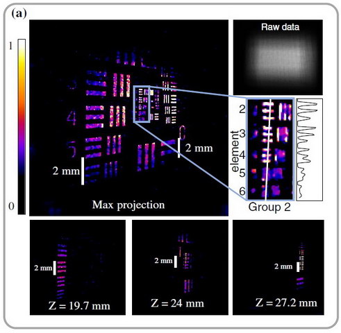 DiffuserCam image of a USAF resolution target tilted at 45° (Credit: UC Berkeley)
The DiffuserCam, like a light field camera, acquires depth information, in addition to the 2D image information, and the reconstruction of the image from the raw data can have any focus positon or depth of field desired. The image shows the reconstruction of a USAF resolution target tilted at 45° relative to the optical axis of the DiffuserCam. The image was reconstructed on a 4.2 MP lateral grid with 128 z-planes and then cropped to 640 × 640 × 50 voxels. The DiffuserCam project page has this and another 3D image posted with motion, making the 3D nature of the reconstructed images clear.
 Motion GIF taken with the DiffuserCam demonstration unit. (Credit: UC Berkeley)
Since the DiffuserCam reconstructs the image from a single frame of raw data from the camera, it has no problem generating moving images, as shown in the Motion GIF above. The authors point out that when the scene is far away from the DiffuserCam relative to its lateral dimensions, as is the case for this movie of the DiffuserCam lab, the image is effectively 2D, as would be expected.
The paper “DiffuserCam: lensless single-exposure 3D imaging” documenting this work can be downloaded for free from the Optical Society of America. The field of computational imaging is very active and this paper cites 45 earlier papers, including both the Hitachi Fresnel Zone Aperture paper and the Rice University FlatCam paper. In fact, the authors thanked Dr. Eric Jonas and the Rice FlatCam team for helpful discussions – the flat camera world is a relatively small world.
Computation is Not Trivial
One of the potential problems computational photography for smartphone use is the “computational” part. One of the claimed advantages of Hitachi’s Fresnel Zone Aperture system is that it is said to reduce the computational needs to reconstruct the image from the sensor data by about 300x compared to previous but similar designs. This may be a major advantage and a 50% reduction in the available light may be a small price to pay for this computational simplicity.
The UC Berkeley authors discuss computational issues, without going into specifics that would allow direct comparison to the Hitachi approach. They do say that there is a mathematical approximation that allows fast and simple computation for FOV angles up to ±15° for their design. For example, the USAF resolution target image above took four hours to reconstruct on a Nvidia Titan X GPU with one algorithm and 1/10 that time (about 24 minutes) with the alternative algorithm. According to Nvidia, “The Nvidia Titan X, featuring the Nvidia Pascal architecture, is the ultimate graphics card.”
If that 300x improvement with the Hitachi approach applies to the 24 minute reconstruction time, and it’s not clear that it does, that would mean it takes 4.8 seconds to reconstruct the image. Still not blazingly fast, nor fast enough for real-time decoding of video. It would take an additional 150:1 improvement in decoding time to get it down to a single frame time of 30Hz video and allow the system to capture real-time video.
The computational issues, including the smartphone battery drain issues associated with the computation, may limit the use of lensless photography and computational imaging in smartphones. On the other hand, with 5G networks coming soon, the raw data could be uploaded to the cloud for reconstruction on a computer 150x as powerful as the Titan X and the reconstructed image downloaded to the phone in a blink of an eye, bypassing the computational issues on a handheld system.
Wouldn’t the cloud computing services like Amazon love that! -Matthew Brennesholtz