Heng Zhang, Qiang Su & Shuming Chen from Southern University of Science and Technology in Shenzhen have recently published an article titled “Quantum-dot and organic hybrid tandem light-emitting diodes with multi-functionality of full-color-tunability and white-light-emission.” The article discusses a hybrid QLED and OLED device that can be used to produce a single pixel with tunable red/green/blue color for a display.
Driven differently, the structure can also be used to produce white light with (potentially) a high color rendering index (CRI), high efficiency and color tunable along the black-body curve over a range of 1500°K to 10,000°K.
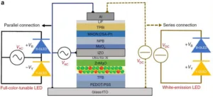
Hybrid OLED/QLED Structure (Credit: Heng Zhang in Nature Communications)
This figure shows the structure of the hybrid device and the two different ways of driving it: parallel and series. The device is built on a glass/ITO base (bottom) and the light is emitted through this surface. Above that is the mixture of red and green CdS quantum dots (QDs) and the various layers needed to drive them. Next is the intermediate connecting electrode (ICE) made of transparent indium–zinc oxide (IZO), produced by sputtering. This is separated from the QLED section of the device with a very thin layer of aluminum, thin enough to be transparent, to protect the QLED layers from the sputtering process. Above that is the blue OLED section, including the MADN:DSA-Ph blue emitting layer and additional layers to support it.
Note that this device, as described by the authors, is not structured horizontally so it represents only one pixel in a display. In a multi-pixel display, the ITO layer on the bottom and the aluminum layer on the top would need to be structured to drive the individual pixels. (Note: it isn’t clear from the paper if the ICE needs to be patterned but the authors describe the device as “two-terminal”, implying it doesn’t need to be patterned.) The intermediate QD and OLED layers would not need to be patterned. According to the authors, this avoids the need to develop ink-jet printing or other means of patterning the QD and the OLED layers. The authors say that single-pixel, color tunable OLED structures were developed in the 1990s but those structures required four independently patterned electrode structures, not the two terminals required by this design.
One of the driving forces behind this design was the fact that red and green quantum dots have very long lifetimes >25,000 hours, when used in a 1000 nit (cd/m²) display. Blue QDs used in a 1000 nit display have a lifetime of about 200 hours, unacceptable for virtually any display application. On the other hand, blue fluorescent organic light-emitting diodes (FL-OLEDs), are relatively stable and have been applied in displays for years. The question is how to combine red and green QDs with blue FL-OLEDS in a single pixel to provide color tunability and long life.
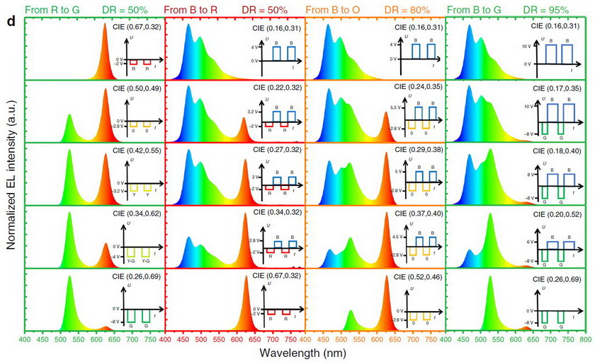 Drive schemes to produce various colors. (Credit: Heng Zhang in Nature Communications)
This figure shows the drive schemes used to change the color emitted, using the parallel connections shown on the left in the first figure. This parallel connection allows the top (FL-OLED) and bottom (QD) sections to be driven by different currents and voltages. This figure is divided into four columns. The first column shows how the drive changes as you go from pure red to pure green. Basically, this is done by increasing the drive voltage because red QDs absorb energy at low voltage while green QDs absorb the energy at high voltages. In this column, there is no drive on the blue OLED at all. The second column shows how drive varies to change from blue to red, the third column the transition from blue to orange and the fourth column from blue to green. The multiple colors are generated color sequentially and the demonstration unit was driven at 100Hz.
One thing that is obvious from this diagram and the spectra it shows in the top and bottom rows of fully saturated colors, the primary colors produced are not very saturated. This is especially true of the blue primary color which has a strong admixture of green light and is more cyan than blue. These primary colors produce a color gamut of about 63% of NTSC, according to the authors. This color gamut is shown in black in the CIE diagram below.
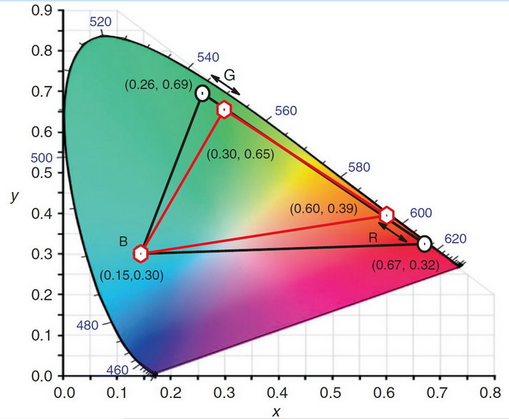 Color gamut of the device (Credit: Heng Zhang in Nature Communications)
There is a second problem not obvious in the drive scheme diagram shown above. While the device, when driven to white, is very bright, about 51,590 nits, the range of brightnesses possible is very small. By accepting reduced saturation for the green and red primaries and a reduced peak brightness of 15,800 nits, as shown by the red triangle in the CIE diagram, a much wider variety of brightnesses can be achieved, as would be needed in a display. This drive system produces about 45% of the NTSC color gamut and is shown in red in the figure. I suspect a pulse-width modulation scheme would allow both more saturated colors and a wide range of brightness levels.
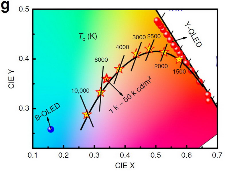 Color adjustability when using the device as a white light source (Credit: Heng Zhang in Nature Communications)
To use the device as a light source, the authors discussed the series configuration, as shown in the top image on the right side. Here the same DC current passes through both the FL-OLED and QD stacks, although the voltage can be redistributed between the two stacks. By adjusting the drive, the color can be shifted along the black body line to produce any desired color temperature of illumination. The authors said that their test device had a poor CRI rating of about 60. They attribute this to the use of a green QD with its peak emission at about 524nm, a value they had chosen to produce optimum display color gamut. For a purpose-built illumination source, they say a green QD with its peak emission around 550 would produce a much higher CRI. This white-light drive scheme can produce 107,000 nits and a maximum external quantum efficiency (EQE) up to 26%.
The authors say that their structure has several advantages. First, it is much more efficient than the White OLED + Color Filter system in use today for large OLED displays. Also, by having all colors of light come from a single pixel, it has about 3x the resolution of a display that has separate red, green and blue sub-pixels. Finally, none of the layers need patterning, except for the top aluminum and bottom ITO layers and, perhaps, the ICE. Since the device as shown has no transistor or other circuitry at the row/column intersection, it could only be driven passive-matrix, limiting the potential display resolution and brightness.
This is clearly an early research result and don’t expect displays or illumination systems to be commercially available any time soon. The paper, which was published on-line on June 6th, can be downloaded, along with its supplementary information, for free from Nature Communications. In fact, since the article was posted just over a month ago, 1716 people have accessed it. I am sure QD,OLED, display and illumination people around the world are currently assessing this design as a potential industrial research project – or product.
Check out the video below – Matthew Brennesholtz